Hello Everyone!!
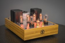
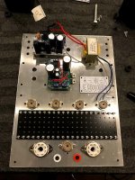
Just finished up this all original design. Been listening a few days and it sounds very good so far.
The issue with the 6S19P is it's gain is very low, 2-3x so a significant signal swing is needed to drive it. Also it's a low voltage high current tube so a low V supply is needed. It's very hard to achieve large signal swings without much voltage.
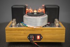
To solve this I designed a PS with 2 voltage rails. So you will see the driver supply is very large compared to the supply for the output stage.
Hope you like the amp. Questions and comments welcome!
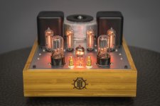
I want to thanks Sean O'Neill for making the beautiful bamboo box.
Just finished up this all original design. Been listening a few days and it sounds very good so far.
The issue with the 6S19P is it's gain is very low, 2-3x so a significant signal swing is needed to drive it. Also it's a low voltage high current tube so a low V supply is needed. It's very hard to achieve large signal swings without much voltage.
To solve this I designed a PS with 2 voltage rails. So you will see the driver supply is very large compared to the supply for the output stage.
Hope you like the amp. Questions and comments welcome!
I want to thanks Sean O'Neill for making the beautiful bamboo box.
Attachments
-
 DUG07672.JPG187.8 KB · Views: 930
 -
 DUG07673.JPG191.9 KB · Views: 900
 -
 DUG07686.JPG218.5 KB · Views: 838
 -
 DUG07688.JPG182.1 KB · Views: 877
 -
 DUG07693.JPG359.4 KB · Views: 1,277
 -
 IMG_9768.JPG110.1 KB · Views: 1,583
 -
 IMG_9665.JPG153.3 KB · Views: 1,143
 -
 IMG_9668.JPG160 KB · Views: 634
 -
 IMG_9826.JPG158.3 KB · Views: 746

Awesome craftsmanship...artwork really, imo.
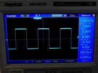
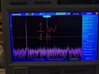
Regarding the graphs- what are we looking at in that hanning window? Or perhaps what do we want to see?
Jim
Regarding the graphs- what are we looking at in that hanning window? Or perhaps what do we want to see?
Jim
Hello Everyone!!
Just finished up this all original design. Been listening a few days and it sounds very good so far.
The issue with the 6S19P is it's gain is very low, 2-3x so a significant signal swing is needed to drive it. Also it's a low voltage high current tube so a low V supply is needed. It's very hard to achieve large signal swings without much voltage.
To solve this I designed a PS with 2 voltage rails. So you will see the driver supply is very large compared to the supply for the output stage.
Hope you like the amp. Questions and comments welcome!
I want to thanks Sean O'Neill for making the beautiful bamboo box.
My question is
Where do I her my hands on one of these Beautiful amps ? Without selling a kidney
Lol
Thanks!! At the moment, I don't sell anything but I hope to be changing that soon!! I'd like to sell a kit I'm developing with a friend! We've been working on it for over a year now. I'll definitely post it here when it gets done!
Wow you did another one with bare wire in that 1920's radio style of wiring, very cool. You must have one of those craft pliers for shaping and bending wire at such perfect 90 degrees.
This is exceptionally elegant in circuit topology, physical design, and build method/quality, and the performance seems pretty excellent, also.
Doug De Young,
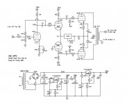
Ditto on nice work. Could you speak about your choice of Za-a = 4k? What power do you get out?
Ditto on nice work. Could you speak about your choice of Za-a = 4k? What power do you get out?
Thanks!! The power out is 8Wpc. The 4k p-p Z was chosen because the 6s19p is a low voltage high current tube and so to get any real power out of it you need to load it with a sufficiently low Z. With a 4k p-p OT each tube will see 2k in class A and 1K in class B. The plate Z is in the same ballpark of 500R so this seems about right.
Doug De Young,
Thanks for the very short and very good explanation of Class AB (The different loads on the plates during A operation versus on one plate at a time during B operation).
I hope everyone who was looking for an explanation of Class AB sees your post.
Thanks for the very short and very good explanation of Class AB (The different loads on the plates during A operation versus on one plate at a time during B operation).
I hope everyone who was looking for an explanation of Class AB sees your post.
I actually have a in depth video about this topic of you find it interesting. 🙂
Plate Curves and Load Lines! - YouTube
Plate Curves and Load Lines! - YouTube
A good oscilloscope study is to have individual 10 Ohm resistors from each cathode to ground (or from the bottom of individual self bias networks to ground).
Load the amplifier output with a resistor.
Put a test tone into the amplifier.
start with a small tone, and increase it slowly.
Connect the 2 channel scope probes from each 10 Ohm resistor to ground.
You can see where the amplifier transitions from Class A to Class AB.
Load the amplifier output with a resistor.
Put a test tone into the amplifier.
start with a small tone, and increase it slowly.
Connect the 2 channel scope probes from each 10 Ohm resistor to ground.
You can see where the amplifier transitions from Class A to Class AB.
Last edited:
Yes, when the avg current of the output tubes begins to rise you are leaving class A.
A good oscilloscope study is to have individual 10 Ohm resistors from each cathode to ground (or from the bottom of individual self bias networks to ground).
Load the amplifier output with a resistor.
Put a test tone into the amplifier.
start with a small tone, and increase it slowly.
Connect the 2 channel scope probes from each 10 Ohm resistor to ground.
You can see where the amplifier transitions from Class A to Class AB.
Quote:
"Yes, when the avg current of the output tubes begins to rise you are leaving class A."
Good info!!
Jim
It is the gentle cutoff of the tubes, as they alternate from one to the other . . .
That is what you will really take note of.
It is a rounded curve to zero current.
That is what you will really take note of.
It is a rounded curve to zero current.
- Home
- Amplifiers
- Tubes / Valves
- 6S19P Push Pull Build