Zero Cool said:I have TWO of Ralph Karsten's (Atma-Sphere) early prototype Circlotron amps!!! Both use 8 6AS7G tubes per channel.

ZC,
Which model amp is that on the picture?
BTW, I have been talking to Ralph about the upcoming OTL kits he plans to start selling again.
-- josé k.
John Broskie (tubecad) offers a solution for the symmetric feedback issue:
http://www.tubecad.com/december2000/page14.html
I like the idea of the "quick, short feedback loop" that "greatly reduces the output impedance and lowers the distortion of the amplifier".
Making the feedback a local business for the output stage seems like a good idea to me.
http://www.tubecad.com/december2000/page14.html
I like the idea of the "quick, short feedback loop" that "greatly reduces the output impedance and lowers the distortion of the amplifier".
Making the feedback a local business for the output stage seems like a good idea to me.
After a few months of salmon fishing and RC flying I´m getting back on the DIY audio track again. Instead of finishing some of my half-built projects I feel it´s time to start working on the circlotron.
Due to the number of tubes and power supplies I will build it as mono blocks and to save a few hours I will "borrow" some chassis parts from an earlier OTL project that probably never will be finished.
I will employ John Broskies output stage topology (see link in the previous post) with 1x 6N6P and 8x 6C19 per channel plus another 6N6P as an LTP input/phase splitter.
http://www.mif.pg.gda.pl/homepages/frank/sheets/113/6/6S19P.pdf
http://www.tubes.ru/techinfo/HiFiAudio/6n6p.html
I´ve spent the evening cutting and drilling alu sheets for the chassis, they will be spray painted tomorrow and left to dry over the weekend before I do anything with them. The paint I´m using dries in a couple of hours but takes a few days to fully harden.
Det där blir ingen lek! Jag kan "spajsa" upp steget åt dig om du vill.
Hoktuna sa att du också lirar. Har ni någon Myspace-sida så vi kan bli "friends"?
Ses snart!
Hoktuna sa att du också lirar. Har ni någon Myspace-sida så vi kan bli "friends"?
Ses snart!
Det får du gärna göra! Jag har inte funderat så mycket över värdena på enskilda komponenter än, så den biten är öppen för förslag.
Spelar bas i två (radikalt olika) band:
http://www.myspace.com/crazybonessweden
http://www.myspace.com/outforretaliation
Synes!
Spelar bas i två (radikalt olika) band:
http://www.myspace.com/crazybonessweden
http://www.myspace.com/outforretaliation
Synes!
Back at home next Tuesday. Just on my way to our summerhouse outside Arvika.
Check Myspace. You have two new requests.
Check Myspace. You have two new requests.
As long as you pick up the horns before 11/8😉
I don´t have the password to any of those Myspace pages, I´m just the bassplayer you know. I´m sure that the rockabilly guys will respond to your request, not so sure about the death metal guys though😀
I don´t have the password to any of those Myspace pages, I´m just the bassplayer you know. I´m sure that the rockabilly guys will respond to your request, not so sure about the death metal guys though😀
OK, you can check my band at :
www.myspace.com/eflatjumptessandersson
It´s enough with the Rockabilly guys, I don´t care so much for the other stuff!
Will call you before coming!
www.myspace.com/eflatjumptessandersson
It´s enough with the Rockabilly guys, I don´t care so much for the other stuff!
Will call you before coming!
The paint is dry, though it wasn´t when I put all 20 tube sockets in place so now it´s a little wrinkled around the bolt heads...😡
FYI: Wiring the heaters for 20 tubes is not the funniest part of a DIY project...
Haven´t heard from Lars for a couple of days.
FYI: Wiring the heaters for 20 tubes is not the funniest part of a DIY project...
Haven´t heard from Lars for a couple of days.
Sorry guys, have been in Arvika, Hotland. Back in town five minutes ago.
Will come back about spajs tomorrow.
Will come back about spajs tomorrow.
Hi reVintage!
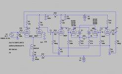
That is pretty much what I have in mind, but there is one thing that doesn´t match Tubecads schematic:
R13/14 makes a voltage divider together with R1/3 which seems to cut the feedback signal down to ~25% of what it should be.
Remove R13/14 and increase R1/3 to 370R and see what happens...?
Thank you for "spajsing" this circuit for me!
This is how I would do it!
It was NOT ment to match Broskies schematic as it seems to be f-cked up! Must be a drawing error as I said in my previous post. Or also I could be the jerk, not to understand his strike of genius ! Anyway I will give it another try tonight as I might have missed something. It could be as simple as that the gnd reference resistors are missing.
My circuit will not work changing R1/R3 as these sets the current through the 6N1Ps to 8mA. And you must have R13/14 as these are for GND reference.
I recommend using a low-mu tube like 6H30 to lower sensitivety.
It was NOT ment to match Broskies schematic as it seems to be f-cked up! Must be a drawing error as I said in my previous post. Or also I could be the jerk, not to understand his strike of genius
! Anyway I will give it another try tonight as I might have missed something. It could be as simple as that the gnd reference resistors are missing.My circuit will not work changing R1/R3 as these sets the current through the 6N1Ps to 8mA. And you must have R13/14 as these are for GND reference.
I recommend using a low-mu tube like 6H30 to lower sensitivety.
Sorry, forget the part about increasing R1/3 to 370R. Tankevurpa😱
I still don´t see the point in R13/14 though, the output stage would still have ground reference through R1 and R3.
Of course I´m talking about shunting R13/14, not removing them!
Regarding the high sensitivity I´m going to use 6N6P (µ~20) in the input and driver stages.
The only weird thing I can see in Broskies circuit is the bias arrangement, I don´t understand the need for a -300V rail when the output tubes only needs something like -25V and cathode bias would be perfectly sufficient for the driver tubes.
Sorry Fuling,
Thought it was 6N1P, will do another sim tonight with the right tube. As 6H30 and 6N6 are "cousins" they might work well.
About gnd reference I ment that it is missing in Broskies circuit.
Thought it was 6N1P, will do another sim tonight with the right tube
. As 6H30 and 6N6 are "cousins" they might work well.About gnd reference I ment that it is missing in Broskies circuit.
I thought about using 6N1P at first but I prefer amps with low input sensitivity (and low feedback if possible).
Now I understand what you mean is wrong with the broskie circuit! He explains the need for ground reference in an earlier article about circlotrons so I guess he just left them out in this one to since the focus is on the feedback circuitry.
What I mean is that those reference resistors can do double duty as cathode (bias) resistors for the driver tubes.
The floating power supplies will then be raised a couple of volts above ground but as they are floating it shouldn´t matter.
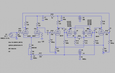
Have spent the last hour trying to sim Broskies circuit with no success.
Anyway, my circuit(below) seems to work. The sim indicates a Zout under 3ohm and a sensitivity of ca 0,4V rms. Thought output before clipping should be higher as this is indicated in TCJ PP calculator. I get 3-4W into 8ohm. With less feedback, higher R13/14, Zout gets higher. 8mA through all 6N6s, 110mA through each 6C19.
Anyway, my circuit(below) seems to work. The sim indicates a Zout under 3ohm and a sensitivity of ca 0,4V rms. Thought output before clipping should be higher as this is indicated in TCJ PP calculator. I get 3-4W into 8ohm. With less feedback, higher R13/14, Zout gets higher. 8mA through all 6N6s, 110mA through each 6C19.
Attachments
- Status
- Not open for further replies.
- Home
- Amplifiers
- Tubes / Valves
- 6S19 Circlotron (OTL)