Dear all,
Some weeks ago I bought a variant of this Dynaco (6n2p+2x6p1p) in DIY kit just to be
amazed that NONE of the input triodes has its cathode DC circuit closed to the ground.
I browsed the net for the schematic diagram and from DOZENS of them ALL BUT ONE WAS CORRECT. As the 100R resistor between cathodes is for negative reaction and not
Rk, find the appropriate Rk for your input valve, halve it and solder it in parallel with (100uF) Ck.
Good luck
Adrian
PS: or replace 100R with two apropriate Rk to the ground and
recalculate the negative reaction loop (1K in paralell with 1nF)
aoncica,
In the dyna schematics earlier in this thread (except Lingwendil's 2nd schematic with the constant current sink, a phase splitter that I like), the input cathode's self bias resistor is actually the 1k feedback resistor that comes from the output transformer secondary, of which secondary, the common end is grounded.
The 100 Ohm cathode resistor is AC (signal) bypassed at the second cathode to ground.
So the feedback resistors are 1k and 100 Ohm, at the first cathode (no 'floating' cathodes in that circuit).
Is your amplifier the same as that?
Please post a correct schematic of your actual amplifier circuit.
Without a schematic of what you started with, your text in Post # 21 is a little hard to understand.
Last edited:
Dear all,
Some weeks ago I bought a variant of this Dynaco (6n2p+2x6p1p) in DIY kit just to be
amazed that NONE of the input triodes has its cathode DC circuit closed to the ground.
I browsed the net for the schematic diagram and from DOZENS of them ALL BUT ONE WAS CORRECT. As the 100R resistor between cathodes is for negative reaction and not
Rk, find the appropriate Rk for your input valve, halve it and solder it in parallel with (100uF) Ck.
Good luck
Adrian
PS: or replace 100R with two apropriate Rk to the ground and
recalculate the negative reaction loop (1K in paralell with 1nF)
My ChiFi kit did not include instructions, so there were certain unknowns that I had to research, then join this forum to discover. In particular- polarity of global feedback...
Per construction-
My previously noted 12W kit didn't have heater wiring populated on PCB... only solder pads that had to be externally wired. Ok- but how hard is it to add those to a PCB?
So don't be surprised that there's some extra investment for the buyer. I have to wonder if the ChiComs assign these board designs to their middle school students for layout practice... so then we are, as we say in states-"guinea pigs" for their products.
Jim
6A3sUMMER
Your explanation is illuminating but the solution (Rfb=Rk) looks to me a little awkward. Isn't also a negativation mismatch between triodes? I'll give it a try
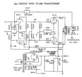
Here it is an excerpt from an old Accrosound transformers data with applications:
Your explanation is illuminating but the solution (Rfb=Rk) looks to me a little awkward. Isn't also a negativation mismatch between triodes? I'll give it a try
Here it is an excerpt from an old Accrosound transformers data with applications:
Attachments
A mistery still unsolved is what Chinese word is translated as "bile" By the automatic translators they are using (?)
Last edited:
Bile or gall-bladder in chinese is written as "胆"
The common name for tube amp in chinese is "胆机“, and "胆” is literally referred as the "tube". a light bulb is usually referred as "灯胆” (especially for Cantonese speakers)as the shape of a light bulb somewhat resembles a gall bladder or a balloon.
A more formal name for "tube" would be "真空管“ (vacuum tube) or "电子管” (electronic tube)
Unfortunate the translation software nowadays sees the word "胆” and translate that to "bile" instead of "tube" . Hence the confusion.