Regarding the CCS's built with Q1 and Q2 - I've run some simulations, and I managed to gain some improvements by adjusting the values - therefore, adjusting the current through the tubes. I am pondering on stabilizing the voltages for the LTP and the Driver by the means of some zeners (to 420 and 300V respectively).
The lack of a capacitor at the CCS transistor bases (to make them slow acting Gyrators) allows the audio signal to vary the tail current dynamically if the tubes are not matched. This may be causing some distortion. Might want to try with a cap there to see if that improves the dist.
The lack of a capacitor at the CCS transistor bases (to make them slow acting Gyrators) allows the audio signal to vary the tail current dynamically if the tubes are not matched. This may be causing some distortion. Might want to try with a cap there to see if that improves the dist.
But wasn't this the original idea - using the two biasing resistors fed from each of the plates of the dual triodes - balancing for the unevenness in gain of the two sides?
BTW, I've tried running a simulation on my amp, which is fairly similar to Mads design. I tried with 100n and 1u capacitors over there, and the distortion actually rises by 0.3% or so as the capacitance value is raised.
Last edited:
A fixed current CCS tail already guarantees that each tube has matched (complementary) voltage swings (in class A). The Gyrator feature then gets the plates to sit at some average voltage for best centering in the linear range.
Removing the cap from the gyrator allows the tail current to vary with signal dynamically. (although if the plates are varying in a complementary fashion already, then the R feedback to the tail CCS should just stay constant anyway)
Varying the tail current changes the gain of the stage. So IF that occurs, then that should produce some distortion. However, that might be a distortion profile that cancels some of the native tube distortion there or elsewhere. So it's just a matter of seeing which variant sounds best or measures best. No particular guarantees.
Acting as a common mode dynamic feedback, it might influence odd harmonics, in which case it might get rid of some odd harmonic distortion that a simple CCS tail produces via tube gm variation.
So it could indeed be better without the cap(s). One would then want to scale the R attenuation, to null the odd harmonic dist.
Hmm, it is converting the common mode output V to tail current variation, but opposite to what a tail resistor tuned for 3rd harmonic dist. nulling would do. This might be making 3rd harmonic worse. ??
A test would be interesting to see what it does to 3rd harmonic dist. when the cap is removed. The results may depend on whether there are triodes or pentodes up to top also.
Last edited:
I think it is better that you design a -15V for Q1 and Q2. It was got from -60V by a regulator circuit.
I think it is better that you design a -15V for Q1 and Q2. It was got from -60V by a regulator circuit.
Why would we want to do that?
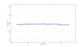
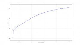
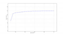
Attached are measurements made with a HP8903A audio analyzer.
Frequency response plot, output level at 1 kHz and a THD+n which raises a few questions to be investigated further with a scope to see what kind of noise it it.
Frequency response plot, output level at 1 kHz and a THD+n which raises a few questions to be investigated further with a scope to see what kind of noise it it.
Attachments
Hi Mads,
Indeed, rather strange that increase in the noise above 500Hz...
A question, if you don't mind: what is the size of the OPT core?
Indeed, rather strange that increase in the noise above 500Hz...
A question, if you don't mind: what is the size of the OPT core?
Hi Mads,
Indeed, rather strange that increase in the noise above 500Hz...
A question, if you don't mind: what is the size of the OPT core?
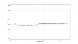
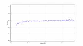
I will measure the physical size of it later tonight. That measurement might have a fluke, here is the same measurement, but separate, just as dB instead of %.
Measurements are 20 Hz to 30 kHz, 0.5V, 100 steps per decade.
Attachments

All the above measurements are invalid, dummy load was not properly connected so it is basically running "open loop" into the 100K impedance of the analyzer.
The manual MOSFET linear regulation part of the power supply for the screens have also been scrapped and replaced by a resistor. It was stable and fine at operation, but every now and then it would short circuit on power up of the amplifier.
After playing around with the audio analyzer looped back to itself, I forgot I had it set for 6V output and hooked the amplifier up for a FR test. This resulted in OPT arcing over and I had to take it apart, no visible damages, but secondary side measures only half the DC resistance as the OPT I have for the other mono block, I will have to hi-pot test it to see if its really dead or can be saved with a little jiggling and varnish.
What a bummer day, so much destroyed 🙁
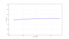
New measurements with a fresh OPT installed, the one that arced gives some spurious 0.5 to 1 Ohm DC resistance on the secondary side, it does not look like its good for anything but brief weighting.
Dummy load was a 8.6 Ohm 200 Watt resistor and thus the output power from the output level test gives some 70 Watt out at 0.5 V in. The other tests are done at 0.5 V input too.
I had the amplifier hooked up to my JBL 4333s for the first time and it is now obvious that there is a reason for the high thd+n measurements, there is a great deal of noise, still not sure which kind, but sounds like white and harmonic.
It plays pretty well, not too sure about bass yet, seems to vary a lot by the music, Metallica still has evil deep punch, whereas some other artists are flattened a bit.
Attachments
Hi Mads,
Have you had the chance to take the size of the core of your OPT? I'd be interested to compare it with what I have. Thanks!
Have you had the chance to take the size of the core of your OPT? I'd be interested to compare it with what I have. Thanks!
Hi Mads,
Have you had the chance to take the size of the core of your OPT? I'd be interested to compare it with what I have. Thanks!
I am sorry that I forgot to do it the other night, being a family got in the way 🙂
It measures, as seen on this most recent picture, 60 mm wide, 100 mm deep and 80 mm in height.
Attachments

I am sorry that I forgot to do it the other night, being a family got in the way 🙂
It measures, as seen on this most recent picture, 60 mm wide, 100 mm deep and 80 mm in height.
Yeah, I can understand that statement about family, I'm in the same boat (with a 2yo) 🙂
So you've got an EI102/60 core, which is around 20cm^2. Some rather brute calculations tell that it's good for 100W @20Hz. I've got only EI102/53 core, 17cm^2, like 100W@26Hz.
I had the amplifier hooked up to my JBL 4333s for the first time and it is now obvious that there is a reason for the high thd+n measurements, there is a great deal of noise, still not sure which kind, but sounds like white and harmonic.
That might be the reason why your mosfets kept blowing up.
Last edited:
- Status
- Not open for further replies.
- Home
- Amplifiers
- Tubes / Valves
- 6P45S 50W mono block tube amplifier