The idea to build these amplifiers came with purchasing a set of old studio monitors, the legendary JBL 4333. These 75 Watt speakers with 15″ bass drivers needed a amplifier that could deliver some more punch than my 20 Watt EL34 amplifier.
I had twenty used tubes to use, ordered the russian equivalent of the 6SN7 to stay with the theme and had some old ECC83 in the big tube box.
I based the design on a rebuild of a old Easteuropean amplifier, the APX-100, Claus Byrith EL34 and a amplifier called KT88 Beastie from user Kruesti here on diyaudio.com using long tailed pair for balancing the pre amplifier and phase splitter stages.
I plan to build in a AVR microcontroller for showing voltages and currents on a LCD, making output stage adjustments/balancing easier and emergency shutdown to protect speakers automatic.
The complete article with all details, picture and information: 100W 6P45S monoblock tube amplifier | Kaizer Power Electronics
Attachments
Last edited:
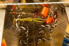
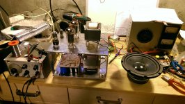
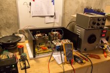
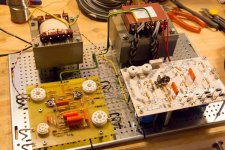
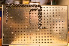
The prototype is built from scrap materials and BirdNestTechnology 2.0 🙂
The prototype finally working, amplifying at 475VDC with 1000mV over the cathode resistor, somewhere around 45-50 Watt output power.
I spend a long time making many tweeks against parasitic oscillations that turned out to be bad output tubes. But I went through 7 output tubes that did not work properly before I got it running. Went straight from the bench to start working on the uTracer3 to avoid such waste of time in the future 🙂
A short video of the amplifier working: 6P45S tube amplifier - YouTube
Attachments
Looks very nice 🙂
There are a few points I would like the draw your attention on 😉
Better put some resistors in parallel with the electrolytics-pairs in the power supply.Otherwise the voltage will divide according to there leak resistances,probably not equal.
Why C2,C3=470n on 1M and C4,C5=100n on 220k ,I would invert that.
It seems to me that Q1 is starving there(not much of a current source),perhaps R7,R8 smaler ?
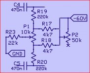
And last the bias circuit.If one of the pot.meters fail (no center contact) the bias goes to 0volt.The tubes doesn't like that 😱 .
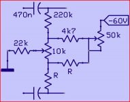
Here a suggestion on how to avoid it,like this a fault gives max.bias.
Mona
There are a few points I would like the draw your attention on 😉
Better put some resistors in parallel with the electrolytics-pairs in the power supply.Otherwise the voltage will divide according to there leak resistances,probably not equal.
Why C2,C3=470n on 1M and C4,C5=100n on 220k ,I would invert that.
It seems to me that Q1 is starving there(not much of a current source),perhaps R7,R8 smaler ?
And last the bias circuit.If one of the pot.meters fail (no center contact) the bias goes to 0volt.The tubes doesn't like that 😱 .
Here a suggestion on how to avoid it,like this a fault gives max.bias.
Mona
Attachments
The prototype finally working, amplifying at 475VDC with 1000mV over the cathode resistor, somewhere around 45-50 Watt output power.
[/url]
I have built three (3) different amplifiers with 6P45S/PL519/JJEL509.
Two with normal PP-topology and one Circlotron.
I reached essentially higher power levels. With 1k8 OPT, the power level is some 170 W and with 4 k OPT about 100 W.
According to my tests the optimum quiescent current (lowest THD) is about 45...55 mA. Your cathode current seems to be 100 mA/tube.
This exceeds the specified max. PD a lot. Or have I misunderstood something ?
How did you came into the conclusion to use such high current ?
What sort of THD values you have ?
Still it it very difficult to understand how it is even possible to construct an amplifier giving only 50 W with the conditions you have told.
Below the schematic of my PP-amps.
The first is 170 W and the second 100 W version.
An externally hosted image should be here but it was not working when we last tested it.
An externally hosted image should be here but it was not working when we last tested it.
Last edited:
Hi,
what's the use of diriving the CCSs' base voltages (and thus the common cathode currents) from the anodes in both differential pairs? Kind of bias servo?
Best regards!
what's the use of diriving the CCSs' base voltages (and thus the common cathode currents) from the anodes in both differential pairs? Kind of bias servo?
Best regards!
Ketje and Kay Pirinha:
I used the schematic that Kruesi posted in the bottom of this thread: http://www.diyaudio.com/forums/tubes-valves/71300-photo-gallery-523.html he explains the reasons for the design here http://www.diyaudio.com/forums/tubes-valves/71300-photo-gallery-525.html#post3537462
I do have balancing resistors on the power supply, just forgot to put them in the schematic, thanks for noticing!
I will for sure implement the bias network like you suggested, but in any case, I would catch such a failure with the microcontroller emergency shutdown that I will add.
Artosalo:
You did not misunderstand anything, I did. As I used Ohms law to calculate the plate current I brain farted and did the same for output power without taking plate load into account. I do not fully understand the math behind tube amplifier design and try to learn as I build. So having it adjusted for 100mA is a mistake and it was never driven that hard as I tested with a very low amplitude input signal, no red plates 🙂
Could you please point me in the right direction of which book to start with? Books: Technical books online
There is an error in the drawing 😱 ,the 50k potm can't do anything like that.An update,And last the bias circuit.If one of the pot.meters fail (no center contact) the bias goes to 0volt.The tubes doesn't like that 😱 .
Here a suggestion on how to avoid it,like this a fault gives max.bias.
Mona
Mona
Attachments
Ketje: I tried simulating the two different bias adjustment circuits, the original one I use makes for a nice logarithmic curve voltage that evenly distributes between the two legs, whereas your 2nd suggested jumps suddenly. I will use my original circuit and possible potentiometer failure will be catched by the microcontroller watching cathode resistor voltage drop.
This is much more in the league of a 100 Watt amplifier, thanks to Artosalo for helping me.
I also updated the schematics as attached in this post (how do i delete the old outdated?)
This is much more in the league of a 100 Watt amplifier, thanks to Artosalo for helping me.
I also updated the schematics as attached in this post (how do i delete the old outdated?)
Attachments
Last edited:
New link to my homepage with full article: 100W 6P45S monoblock tube amplifier | Kaizer Power Electronics
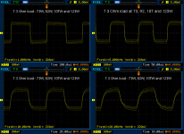
Second performance measurements after NFB capacitor is changed from 1nF (41kHz cutoff) to 0.47nF(87kHz cutoff), the bandwidth of the amplifier was increased and clipping occurs at higher power than earlier measurements.
Thanks to Arto Salo for helping me with these improvements.
Clipping occurred at 39.2V over 7R3 resistor.
Attachments

Last edited:
It has been a while since I last gave an update, due to the fact that I became a father in February 2014, time has be scarce 🙂
All construction pictures available at: 100W 6P45S monoblock tube amplifier | Kaizer Power Electronics
June 2014 I started putting the final version together after having tested enough on the prototype.
November 2014 I was done building and could start the first power up tests, adjustments of voltages, balances etc and test with a signal generator.
A few of the troubles met along the way:
- Too little load on the VR tubes, fixed with load resistors to ensure a suitable minimum load.
- Screen supply 500V MOSFET died from voltage spike at turn on, switched to a 800V MOSFET.
- Hum issues have been lessened with additional screen on the input coax cable and mounting input coupling capacitor with leg connected to outer film of the capacitor to the lowest impedance towards ground.
Signal generator test of the amplifier: https://www.youtube.com/embed/MFLInENxC2E
Future improvements account for:
- Tilting and turning OPT in respect to PT.
- Upgrading to fast diodes instead of regular slow rectifiers.
- C or RC snubbering on the rectifiers.
- NTC inrush current limitation.
Attachments
In the meanwhile, did you change R14 and R15 ? Because with those values (10k and 1k) there is no voltage left for the Q2 to function.(emetter 8V and collector 7V5)
If you make R14=5k1 and R15=470R the collector stays at 7V5 but the emitter goes to 3V75.Leaving also 3V75 for Q2.
Mona
If you make R14=5k1 and R15=470R the collector stays at 7V5 but the emitter goes to 3V75.Leaving also 3V75 for Q2.
Mona
In the meanwhile, did you change R14 and R15 ? Because with those values (10k and 1k) there is no voltage left for the Q2 to function.(emetter 8V and collector 7V5)
If you make R14=5k1 and R15=470R the collector stays at 7V5 but the emitter goes to 3V75.Leaving also 3V75 for Q2.
Mona
Are you sure? I am using these values in a very similar amp, but using 6N1P as driver tube. It is functioning well for me. Oh, and the transistor is MPSA42.
In the meanwhile, did you change R14 and R15 ? Because with those values (10k and 1k) there is no voltage left for the Q2 to function.(emetter 8V and collector 7V5)
If you make R14=5k1 and R15=470R the collector stays at 7V5 but the emitter goes to 3V75.Leaving also 3V75 for Q2.
Mona
I measured the voltages on the amp last night and Mona is right, emitter and collector is at roughly 7,5-8V each.
I changed to 4K4 and 440R but did not have time to test it last night, will adjust the balance if needed and measure again as soon as possible.
Hi Mads,
In my amp with 6P36S the G2 supply is derived from a center tap from the main HT winding. Then I use a MOSFET voltage dropper to have around 205V. This way the transistor won't warm up at all. The B+ is some 500V under full load.
It seemed to perform pretty well so far!
In my amp with 6P36S the G2 supply is derived from a center tap from the main HT winding. Then I use a MOSFET voltage dropper to have around 205V. This way the transistor won't warm up at all. The B+ is some 500V under full load.
It seemed to perform pretty well so far!
Hi Mads,
In my amp with 6P36S the G2 supply is derived from a center tap from the main HT winding. Then I use a MOSFET voltage dropper to have around 205V. This way the transistor won't warm up at all. The B+ is some 500V under full load.
It seemed to perform pretty well so far!
I do not have a CT on the HT winding, so I used the first voltage after the rectifiers so not to disturb the voltages after the dropping resistors for other parts of the amplifier and I would also not unbalance the two capacitors in series for the 475V HT by taking screen apply from just one of them.
Update from two days ago:
Further investigation of hum issues was conducted by waving a isolated 1000VDC rated screw driver around in proximity of different components while watching the secondary side of the output transformer on my oscilloscope.
I identified two vulnerable places where a great deal of noise could be induced through capacitive coupling and there is also sensitive to noise through induction from magnetic fields.
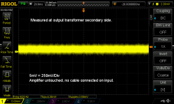
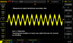
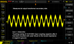
The first issue was a small part of the signal line in coaxial cable that was not shielded. Explanations are written on each screenshot from the oscilloscope. The first pictures show the output without any interference with the circuit. The second shows the effect of touching the isolation on the part of the signal line in cable that was not shielded.
Further investigation of hum issues was conducted by waving a isolated 1000VDC rated screw driver around in proximity of different components while watching the secondary side of the output transformer on my oscilloscope.
I identified two vulnerable places where a great deal of noise could be induced through capacitive coupling and there is also sensitive to noise through induction from magnetic fields.
The first issue was a small part of the signal line in coaxial cable that was not shielded. Explanations are written on each screenshot from the oscilloscope. The first pictures show the output without any interference with the circuit. The second shows the effect of touching the isolation on the part of the signal line in cable that was not shielded.
Attachments
Update from two days ago:
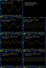
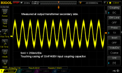
The second issue was the coupling capacitor in the input circuit before the pre-amplifier. The yellow wave form with the highest amplitude show the induced noise by touching it as it was installed.
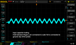
The two blue wave form screenshots show the test to locate the pin connected to the outer foil layer in the capacitor, the capacitor is simply connected to the signal and ground of the oscilloscope probe and squeezed around with your fingers. Switch the connections around to perform it at reverse polarity.
The wave form with the lowest amplitude tells us that the pin currently connected to the ground clip is the pin connected internally to the outer foil layer in the capacitor. This outer layer will also function as a shield in high impedance circuits and that pin should be connected to ground or the path with lowest impedance towards ground.
Now the question is, did it help? Measurable yes, on any audible hum performance heard with a human ear... not really 🙂
The second issue was the coupling capacitor in the input circuit before the pre-amplifier. The yellow wave form with the highest amplitude show the induced noise by touching it as it was installed.
The two blue wave form screenshots show the test to locate the pin connected to the outer foil layer in the capacitor, the capacitor is simply connected to the signal and ground of the oscilloscope probe and squeezed around with your fingers. Switch the connections around to perform it at reverse polarity.
The wave form with the lowest amplitude tells us that the pin currently connected to the ground clip is the pin connected internally to the outer foil layer in the capacitor. This outer layer will also function as a shield in high impedance circuits and that pin should be connected to ground or the path with lowest impedance towards ground.
Now the question is, did it help? Measurable yes, on any audible hum performance heard with a human ear... not really 🙂
Attachments

More information and also a video of it playing music: https://www.youtube.com/watch?v=iflcY5jCHro
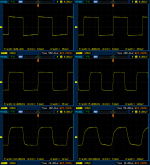
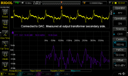
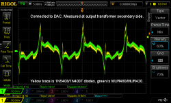
All wave forms are from the secondary side of the output transformer.
The first oscilloscope screenshot shows a Fast Fourier Transform (FFT) analysis of the noise generated by the normal diodes for the 340VAC high voltage supply 1N5408 and 40VAC bias supply 1N4007.
The second oscilloscope screenshot shows the difference between normal diodes like 1N5408/1N4007 that have reverse recovery times around 2uS and fast diodes like MUR480/MUR420 that have reverse recovery times around 50nS is shown in the oscilloscope screenshot with yellow and green wave forms. The spike amplitude is around 15% less but the overall 50Hz hum at the positive half cycle is a little more prominent. Changing the diodes gave a difference in the sound from the switching spikes.
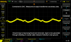
The third oscilloscope screenshot shows the much reduced noise levels after a ground loop formed from star ground point to signal input plug was removed and along with the much shorter switching spikes from the new fast diodes.
Audible it appeared like 90% of the hum disappeared. The greatest performance gain was however from removing a ground loop, the faster diodes did not have such a dramatic effect, it was hear able, but not on the magnitude of removing the ground loop.
Mona: I have now tested the amplifier with the changed Q2 resistors and I had to adjust bias balance further to one side, so if the splitter is now more balanced than before it is infact the output tubes that are not matched that great anyway.
All wave forms are from the secondary side of the output transformer.
The first oscilloscope screenshot shows a Fast Fourier Transform (FFT) analysis of the noise generated by the normal diodes for the 340VAC high voltage supply 1N5408 and 40VAC bias supply 1N4007.
The second oscilloscope screenshot shows the difference between normal diodes like 1N5408/1N4007 that have reverse recovery times around 2uS and fast diodes like MUR480/MUR420 that have reverse recovery times around 50nS is shown in the oscilloscope screenshot with yellow and green wave forms. The spike amplitude is around 15% less but the overall 50Hz hum at the positive half cycle is a little more prominent. Changing the diodes gave a difference in the sound from the switching spikes.
The third oscilloscope screenshot shows the much reduced noise levels after a ground loop formed from star ground point to signal input plug was removed and along with the much shorter switching spikes from the new fast diodes.
Audible it appeared like 90% of the hum disappeared. The greatest performance gain was however from removing a ground loop, the faster diodes did not have such a dramatic effect, it was hear able, but not on the magnitude of removing the ground loop.
Mona: I have now tested the amplifier with the changed Q2 resistors and I had to adjust bias balance further to one side, so if the splitter is now more balanced than before it is infact the output tubes that are not matched that great anyway.
Attachments
Last edited:
- Status
- Not open for further replies.
- Home
- Amplifiers
- Tubes / Valves
- 6P45S 50W mono block tube amplifier