I'm a bit confused by the anode dissipation figures in the 6P41S datasheet. It says:
"Maximum design (calculated) power dissipation 12W"
"Minimum power dissipation 14W"
But then it say we can get 60W in class B push-pull. Does anybody know the real maximum anode power dissipation figure?
Thanks!
"Maximum design (calculated) power dissipation 12W"
"Minimum power dissipation 14W"
But then it say we can get 60W in class B push-pull. Does anybody know the real maximum anode power dissipation figure?
Thanks!
Got it, thank you! That tube is a beast in a 9 pin socket!See post #50.
6P41s vs 7868
I see, same socket as the 6P45, right?That's a Magnoval 9 pin socket. And many tubes DO red plate at 2x the datasheet spec. But 6P41S is cheap at least.
It is cheap indeed, plenty available, and does not require high voltage. Interesting tube.
60 watts in class B with 500 volts and 8k a-a is bull ****. It’s 48 watts, if the knee voltage is 60 volts. Anode dissipation is only 12.5 watts per tube for those operating conditions, but could be more at quiescent. Typically 7868s run more dissipation at idle than at power.
I don't think this tube is good for high plate voltages. Is a high current tetrode, great for low voltage design.
I was playing with the curves in the datasheet, should be able to achieve 30W AB1 with 2400 p-p and 240V, Iq 50...75mA, assuming 25W max anode dissipation. Pure class B is not suitable for me, distortion would be huge.
I was playing with the curves in the datasheet, should be able to achieve 30W AB1 with 2400 p-p and 240V, Iq 50...75mA, assuming 25W max anode dissipation. Pure class B is not suitable for me, distortion would be huge.
I did a lot of testing with 6P41S and built three amps with them.
My conclusion was they were rated between 20W and 25W anode dissipation. I found it took nearly 30W to red plate the tube.
The datasheet specs were for sweep tube operation, not class A or AB audio operation.
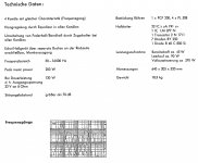
Attached is my translation of the datasheet.
My conclusion was they were rated between 20W and 25W anode dissipation. I found it took nearly 30W to red plate the tube.
The datasheet specs were for sweep tube operation, not class A or AB audio operation.
Attached is my translation of the datasheet.
Attachments
Thank you. I do have the original Russian datasheet....
The datasheet specs were for sweep tube operation, not class A or AB audio operation.
Attached is my translation of the datasheet.
I don't think this tube is good for high plate voltages. Is a high current tetrode, great for low voltage design.
I was playing with the curves in the datasheet, should be able to achieve 30W AB1 with 2400 p-p and 240V, Iq 50...75mA, assuming 25W max anode dissipation. Pure class B is not suitable for me, distortion would be huge.
The Russian 6P41S tube was primarily designed to operate in the output stage of a vertical deflection of ~ 110 ° color TVs of larger screen diameters (at that time they were diagonals of ~ 65-75cm!), and served as a model for designers EL508 (PL508).
At the same time, they tried to make the best use of a well-made tube (more robust and stronger than the EL508), so they adjusted the pin layout to the expensive EL506 in order to serve as a replacement (or in new constructions?) in audio amplifiers.
I wouldn’t agree that the 6P41S doesn’t work well and stably at higher anode voltages (it works well even at lower supply voltages at higher currents!) Because I once used it in a “Hohner Champion” amplifier (as a replacement for the PL508).
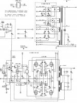
This amplifier uses 4 pieces of PL508 in the push-pull output stage and PCF200 as the phase splitter.
These tubes proved difficult to supply, so I added a small 6.3V / 6A heating transformer to the amplifier, replaced the 10-pin PCF200 socket with a 9-pin (Noval; I actually removed the existing socket from the printed circuit board and put a noval socket on the spacer which I short-circuited with wires to the main printed circuit board) and replaced a few resistors to fit the phase splitter for the ECF80 tube (or the Russian 6F1P).
The original amplifier has a supply voltage of almost ~ 700V at rest (no signal), but at maximum power this voltage drops to ~ 600-620V. The supply voltage of G2 for PL508 was ~ 260V, but for 6P41S I stabilized it to ~ 200V using a simple stabilizer (2 Zener diodes of 100V and FET IRFG820).
6P41S worked without that stabilizer, but with the stabilizer the distortions were significantly lower.
"Hohner Champion" with output 4xPL508 is declared for power of 130W (32V sine at 8 Ohms, which I never had a chance to measure, nor distortions because I didn’t have a chance to try that amp in its original state with new tubes!), but with 4x6P41S I got ~ 120W with ~ 5% distortion without any traces of overheating and red overheating of the plate or G2.
davorin,
Thanks for the interesting schematic you posted and your discussion of the conversion of tubes used, including from PCF200 to ECF80/6F1P. I happened to have several ECF200 tubes (and sockets), as well as 6P41Ss. I would like to build something with them sometime and your conversion of the Hohner Champion circuit looks very interesting.
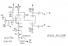
If OP would allow a small diversion, one question about the schematic - why is the anode and cathode resistors (150k and 100k respectively) on the phase splitter different by 50k? One could expect a small difference, or a trimmer added to adjust the AC splitter action, but 50k is more than I expected. Do you know why? What did you use after your conversion to 6F1P.
Thanks for the interesting schematic you posted and your discussion of the conversion of tubes used, including from PCF200 to ECF80/6F1P. I happened to have several ECF200 tubes (and sockets), as well as 6P41Ss. I would like to build something with them sometime and your conversion of the Hohner Champion circuit looks very interesting.
If OP would allow a small diversion, one question about the schematic - why is the anode and cathode resistors (150k and 100k respectively) on the phase splitter different by 50k? One could expect a small difference, or a trimmer added to adjust the AC splitter action, but 50k is more than I expected. Do you know why? What did you use after your conversion to 6F1P.
Impressive! Do you know the plate to plate load in this Hohner Concert amplifier?
Best regards!
I'm not 100% sure (it was more than ~ 20 years ago!), but I think the Raa of that transformer was 5 kOhm. So if we take into account that there were 4 output tubes (2 in parallel), for the PL508 pair the primary impedance was Raa ~ 10 kOhm which is understandable considering the high supply voltage. Maybe it wasn't the maximum appropriate impedance for the 6P41S so the maximum wasn't extracted from them, but both me and the amp user were pleased.
Subsequently, the replacement of the tubes in the amplifier was simple and cheap because the 6P41S and 6F1P are still like that today.
The Russian 6P41S tube was primarily designed to operate in the output stage of a vertical deflection of ~ 110 ° color TVs of larger screen diameters (at that time they were diagonals of ~ 65-75cm!), and served as a model for designers EL508 (PL508).
At the same time, they tried to make the best use of a well-made tube (more robust and stronger than the EL508), so they adjusted the pin layout to the expensive EL506 in order to serve as a replacement (or in new constructions?) in audio amplifiers.
I wouldn’t agree that the 6P41S doesn’t work well and stably at higher anode voltages (it works well even at lower supply voltages at higher currents!) Because I once used it in a “Hohner Champion” amplifier (as a replacement for the PL508).
This amplifier uses 4 pieces of PL508 in the push-pull output stage and PCF200 as the phase splitter.
These tubes proved difficult to supply, so I added a small 6.3V / 6A heating transformer to the amplifier, replaced the 10-pin PCF200 socket with a 9-pin (Noval; I actually removed the existing socket from the printed circuit board and put a noval socket on the spacer which I short-circuited with wires to the main printed circuit board) and replaced a few resistors to fit the phase splitter for the ECF80 tube (or the Russian 6F1P).
The original amplifier has a supply voltage of almost ~ 700V at rest (no signal), but at maximum power this voltage drops to ~ 600-620V. The supply voltage of G2 for PL508 was ~ 260V, but for 6P41S I stabilized it to ~ 200V using a simple stabilizer (2 Zener diodes of 100V and FET IRFG820).
6P41S worked without that stabilizer, but with the stabilizer the distortions were significantly lower.
"Hohner Champion" with output 4xPL508 is declared for power of 130W (32V sine at 8 Ohms, which I never had a chance to measure, nor distortions because I didn’t have a chance to try that amp in its original state with new tubes!), but with 4x6P41S I got ~ 120W with ~ 5% distortion without any traces of overheating and red overheating of the plate or G2.
Wow, that's very impressive. Is a shame there are no curves reaching the high voltage area in the datasheet, however it should not be difficult to extrapolate. My main issue is that the datasheet states "maximum anode voltage" 400V. From that to 700 is almost double.
My other reason to use low voltage is that I have no high powered OPTs, I was planning to experiment with toroids first, then see how it goes.
The Russian 6P41S tube was primarily designed to operate in the output stage of a vertical deflection of ~ 110 ° color TVs of larger screen diameters (at that time they were diagonals of ~ 65-75cm!), and served as a model for designers EL508 (PL508).
At the same time, they tried to make the best use of a well-made tube (more robust and stronger than the EL508), so they adjusted the pin layout to the expensive EL506 in order to serve as a replacement (or in new constructions?) in audio amplifiers.
I wouldn’t agree that the 6P41S doesn’t work well and stably at higher anode voltages (it works well even at lower supply voltages at higher currents!) Because I once used it in a “Hohner Champion” amplifier (as a replacement for the PL508).
This amplifier uses 4 pieces of PL508 in the push-pull output stage and PCF200 as the phase splitter.
These tubes proved difficult to supply, so I added a small 6.3V / 6A heating transformer to the amplifier, replaced the 10-pin PCF200 socket with a 9-pin (Noval; I actually removed the existing socket from the printed circuit board and put a noval socket on the spacer which I short-circuited with wires to the main printed circuit board) and replaced a few resistors to fit the phase splitter for the ECF80 tube (or the Russian 6F1P).
The original amplifier has a supply voltage of almost ~ 700V at rest (no signal), but at maximum power this voltage drops to ~ 600-620V. The supply voltage of G2 for PL508 was ~ 260V, but for 6P41S I stabilized it to ~ 200V using a simple stabilizer (2 Zener diodes of 100V and FET IRFG820).
6P41S worked without that stabilizer, but with the stabilizer the distortions were significantly lower.
"Hohner Champion" with output 4xPL508 is declared for power of 130W (32V sine at 8 Ohms, which I never had a chance to measure, nor distortions because I didn’t have a chance to try that amp in its original state with new tubes!), but with 4x6P41S I got ~ 120W with ~ 5% distortion without any traces of overheating and red overheating of the plate or G2.
OP enjoys technical discussions, go for itdavorin,
Thanks for the interesting schematic you posted and your discussion of the conversion of tubes used, including from PCF200 to ECF80/6F1P. I happened to have several ECF200 tubes (and sockets), as well as 6P41Ss. I would like to build something with them sometime and your conversion of the Hohner Champion circuit looks very interesting.
If OP would allow a small diversion, one question about the schematic - why is the anode and cathode resistors (150k and 100k respectively) on the phase splitter different by 50k? One could expect a small difference, or a trimmer added to adjust the AC splitter action, but 50k is more than I expected. Do you know why? What did you use after your conversion to 6F1P.
")
No doubt 6P41S is very powerfull , just by looking at the heater current 1,1A
Of course heat dissipation in a noval tube is limited so if you listen for long at such high power level you will need a stock of them
See post #4. It's Magnoval.
davorin,
Thanks for the interesting schematic you posted and your discussion of the conversion of tubes used, including from PCF200 to ECF80/6F1P. I happened to have several ECF200 tubes (and sockets), as well as 6P41Ss. I would like to build something with them sometime and your conversion of the Hohner Champion circuit looks very interesting.
If OP would allow a small diversion, one question about the schematic - why is the anode and cathode resistors (150k and 100k respectively) on the phase splitter different by 50k? One could expect a small difference, or a trimmer added to adjust the AC splitter action, but 50k is more than I expected. Do you know why? What did you use after your conversion to 6F1P.
I used ECF80 because I had them and PCF200 didn’t! The Russian replacement for the ECF80 is the 6F1P was then (and still is today!) very cheap, and there are 6BL8s that are also available. Due to the replacement of the output tubes, I had to insert an additional 6.3V heating transformer into the amplifier, so then the heating of the PCF80 would become more complicated.
I didn't study the circuit with PCF200 and analyze the connection because the existing one in the amplifier was weak and worn out, and I didn't have a new one for rehearsals, and the base itself looked old and worn out, so I easily decided to replace it.
Basically the circuit is actually almost the same, but the resistor values are not, but that was not a problem when replacing them on the printed circuit board.
Attached is a diagram of a phase turntable with ECF80 as I think I built into the amplifier (maybe with minimal changes in component values!), and maybe I had small corrections of the 24 kOhms resistor value in the 300V rectifier as well as the negative feedback resistor value connection to the secondary of the output transformer.
Attachments
- Home
- Amplifiers
- Tubes / Valves
- 6P41S maximum anode dissipation