Hi please I am looking for some information about russian 6P3S tube.It is equivalent to 5881 or 6L6GC etc etc..What would be a correct load for pushpull amplifier class AB (ultralinear mode)
thanks
thanks
Last edited:
EL34 PP output tranny questions
The other alternative is to use an output tranny from a Ming Da MC34B (6L6 PP), it has a reflected impedance of around 3900 ohms for the 4 ohm tap and 5300 ohms for the 8 ohm tap, but it is around half the size of the Music Angel monster.
I presumed it has triode and ultra-linear mode, my simulation shows it works fine with 5k impedance.
Attachments
What would be a correct load for pushpull amplifier class AB (ultralinear mode)
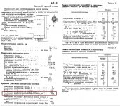
It always makes sense to look what tube manufacturers recommend.
So the answer is from 5k to 6k6.
https://bms.isjtr.ro/sheets/127/5/5881.pdf
Noted 5881, 23-watts Pdissp, 6p3p is only 19watts, one is US made and the other Chinese, what matter is how it sounds to your ears. 5881 is a military tube should be more robust than Chinese 6p3p, the bias keep drifting forever..
Hi please I am looking for some information about russian 6P3S tube.It is equivalent to 5881 or 6L6GC etc etc..What would be a correct load for pushpull amplifier class AB (ultralinear mode)
thanks
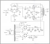
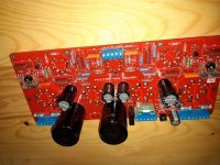
PP-UL with 6P3S, 20w, THD<0,3% without NFB, the transformer impendance is 6,5K, G2 conected to 45%
Attachments
Something is not right in the schematic in post #5.
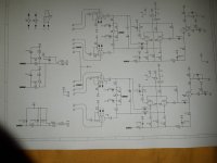
The current through the anode resistor of the first stage is (180 - 82.8) / 100K = 0.972 mA. This fits with the cathode voltage: 0.972 mA x 3770 = 3.66 V. But the current through the 27K resistor in the B+ line is (260 - 180) / 27K = 2.96 mA while it should be the same as the current through the first stage.
The current through one of the anode resistors of the phase inverter is (260 - 208) / 47K = 1.11 mA (note that if the anode resistance would be higher than 47K, this current would be lower than 1.11 mA). So the current through the cathode resistor of 1K5 would be 2 x 1.11 mA. The voltage over this resistor would than be 2.22 mA x 1500 = 3.33 V. But the schematic indicates 7.2 V which gives a current of 4.8 mA.
The current through the 6K8 resistor in the B+ line is (360 - 260) / 6K8 = 14.7 mA. Of that 0.97 mA goes to the first stage and 2.22 mA to the phase inverter. The only current left is the current through the 220K resistor going to the 2N3440. But that current can't be more than 260 / 220K = 1.18 mA. So there is 14.7 - (0.97 + 2.22 + 1.18) = 10.33 mA 'left'.
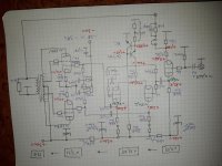
This is the diagram with the values during the tests where some small errors may occur. The voltage in the cathode of the phasse shifter tube is 4,2v on a 1,8k and not 7v as you showed. The resistors in the line werw also modified power supply but by presenting this schme i wanted to communicate the OT data and the percentage of turns in primary for UL. Sorry for these errors and how the PCB was designed by a friend i will ask his permission to post the scematic in digital format used to design the PCB
Attachments

Just FYI --
Russian 6P3S is similar to older 6L6GA. 19W max plate dissipation, max Vp of 360V and max Vg2 of 270V, etc.
Russian 6P3S-EV is more similar to Tung-Sol 5881 or newer 6L6GC. Tung-Sol 5881 had a max plate dissipation of 24W. Sylvania 6L6GC had 30W max plate dissipation. These have max Vp of more like 450V or 500V, max Vg2 of about 400V or 450V.
There will be other differences, of course. I'm sure the rp or gm of a 6P3S will not be exactly like that of a NOS vintage RCA 6L6GA. Nor will the rp or gm of a Russian 6P3S-EV be exactly like that of a Sylvania 6L6GC. But they're in the ballpark.
Last edited:
This is the diagram with the values during the tests where some small errors may occur.
More than 10 mA off is not a small error.
The voltage in the cathode of the phasse shifter tube is 4,2v on a 1,8k and not 7v as you showed.
I didn't show 7 V but you did (7.2 V over 1K5). And 4.2 V over 1K8 gives 2.33 mA, which is just a bit over the 2.22 mA I calculated. So that hardly changes what I wrote about this stage.
The resistors in the line werw also modified power supply but by presenting this schme
Could you than upload the schematic with voltages like it is now?
popa marius,
< 0.3% harmonic distortion at 20 Watts without Global Negative feedback, is excellent!
That proves that Ultra Linear can provide very low distortion by itself.
(UL is a form of negative feedback).
You found the sweet spot for that tube, 45%.
If the damping factor is high enough, and the frequency response is good enough for the application and loudspeakers, no global feedback is necessary.
The design of this amplifier was made for the use of 6P3S and EL34 tubes with the same driver and PCB, the difference being given by the OT impendance, the UL socket and the static operanting point characteristic of the two types of tubes. The adjustment of this point and the fine regulation of the current through CCS lead to a mentioned THD without NFB but on the PCB there is also the possibility to connect NFB. Several amplifiers were built with these tubes, the stongest being the one with EL34 40w at 520v but my opinion is that the 6P3S version sounds the bestpopa marius,
< 0.3% harmonic distortion at 20 Watts without Global Negative feedback, is excellent!
That proves that Ultra Linear can provide very low distortion by itself.
(UL is a form of negative feedback).
You found the sweet spot for that tube, 45%.
If the damping factor is high enough, and the frequency response is good enough for the application and loudspeakers, no global feedback is necessary.
Attachments
So a schematic with voltages of an amplifier was presented in post #5. Less than 0.3 % harmonic distortion at 20 W without GNFB is claimed. But the voltages in the schematic can't be right. The inconsistencies are by no means small.
The schematic in the last post has not enough resolution to clarify things (and there are no voltages indicated in it anyway). What the tubes other than te power tubes are, is still unknown.
How can this all be proof of the very low distortion of ultra linear by itself? This is a diy forum. Is it so strange that I'm still sceptical? And it's not the first time I found inconsistencies in a schematic presented by popa marius. How difficult can it be to present schematics with actual measured voltages?
Whilst messing about with a prototype the other day I got a reading of 0.08% THD - 1khz @ 2.4v RMS. This with a thrown together bench lashup. Frequency response flat from 50hz to 40khz, again, no NFB. So,it's very easy to believe. Don't be so hard on popa marius, he's trying to help, we're all on the same side, this isn't a p***ing contest.It's so excellent that I find it hard to believe
Andy.
It's not about a p***ing contest. It's about presenting faulty schematics on a forum of which a substantial part of the members can't detect those faults. So for me it's about the lack of a sense of responsibility for what one presents here. If one is not sure about (for example) the voltages in a schematic, than just make that clear when you post it.
Veritas odium parit. Absit reverentia vero.
Veritas odium parit. Absit reverentia vero.
Sure, you have the right not to believe the performance data of this amplifier and thanks for pointing out some errors, however the amplifier works exactly as described
I appreciate your know ledge of Latin, I understand message but the technical experiments are not related to literary expression. please show what is so wrong in these measurements to not be credible, thank youIt's not about a p***ing contest. It's about presenting faulty schematics on a forum of which a substantial part of the members can't detect those faults. So for me it's about the lack of a sense of responsibility for what one presents here. If one is not sure about (for example) the voltages in a schematic, than just make that clear when you post it.
Veritas odium parit. Absit reverentia vero.
lots of schematics posted on this forum are tentative or prototype's. Maybe I'm reading you wrong.......It's not about a p***ing contest. It's about presenting faulty schematics on a forum of which a substantial part of the members can't detect those faults
Oh FFS, now it's willy waving. No, wasn't reading you wrongVeritas odium parit. Absit reverentia vero.
Nuff said.I appreciate your know ledge of Latin, I understand message but the technical experiments are not related to literary expression
Last edited:
- Home
- Amplifiers
- Tubes / Valves
- 6P3S Push Pull Load