Hey SVStube, you just exposed your ignorance😉.
Before you post, I suggest you use "search" at diyaudio. In this case you would have found out this topology works great. Michael Koster have designed and built a few.You should also had spiced it to find it also sims great.
It actually works at least as good as a D3a pentode as Schade-driver.
This is the prototype from MJK:
http://www.diyaudio.com/forums/tubes-valves/165221-most-linear-triode-strapped-pentode-7.html#post2204502
Dear revintage.
I wrote my opinion. If you would like to receive the praise, you had to write about it.
I believe only my ears and I have no authority, they have their ears
Hi Ale,
That is how I simulated in LTSpice. Will be interesting to see if it works IRL.
Personally I am not convinced Schade curves will tell it all. If we talk FET or pentode I believe the driver is so much involved that you can not get the answers from the curves alone. My guess is lots of distortion cancellation takes place. Also the Schade stage is part of the drivers local feedback.
Hi Ale,
That is how I simulated in LTSpice. Will be interesting to see if it works IRL.
Personally I am not convinced Schade curves will tell it all. If we talk FET or pentode I believe the driver is so much involved that you can not get the answers from the curves alone. My guess is lots of distortion cancellation takes place. Also the Schade stage is part of the drivers local feedback.
Hi Lars,
Ok will try to trace both set of curves. I will see if I can get the tracer up and running and do this.
Should R1 and R2 be a pot (e.g. 200K) and then calculate feedback based pot position? Interested in looking at the Schade curves anyway...
Cheers,
Ale
Feedback is said to work well in the region of 10%. I would start with a 100k R2 and then try with down to 47k. Wonder how it will work then? Lots of DC on the grid from the anode.
Lars, bad news. Need to fix some bits of the tester so will take me some time as am working on other things now and have limited time. If you are not in a rush, I hope I can pick this up again soon
Ale
Ale
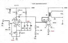
A bit of action over on the Russian board
https://sites.google.com/site/sever...esevernyjpribojzimafotosessii/usiliteli/6p21s
ñõåìà SE 6Ï21Ñ - Ñòðàíèöà 4
TANk likes it "По звуку в триоде, на мой ух, лампа не хуже 6С4С. Друг, для которого делался этот макет очень хотел именно прямонакальный усилитель и он остался им доволен. Забрал, хотел сам потом сделать красивый корпус, но поскольку усилитель у него постоянно "на слуху" новый корпус ему явно не грозит"
"As for the sound in triode, to my ears the tube is not inferior to the 6C4C..."
There's a schematic also which has 300v on the plate - my 425v was clearly the wrong operating point. I should give it another go I suppose. I note that the resistor between screen and plate is more like 430 ohms - I was using 100 ohms.
Although the last post has a schematic running it at 400v and 45mA which is exactly what I was doing, and with a 4P1L driver.
Andy
Attachments
Last edited:
No hurry for me. Take your time. Hope your tester is repairable.
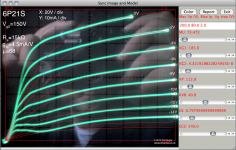
Hi Lars,
Here they are. The model is using Dmitry's pentode tool, and fit them the best I could. I'm good at the triode model, but fitting the tetrode is a challenge. Anyway, do you think is good enough for the basic test?
Cheers,
Ale
Attachments
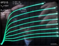
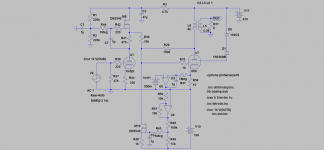
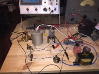
My test setup for 6P21S:
I got almost 5W out of it in triode mode with 350V/55mA across the tube, a 3,5k plate load (with CFB from the 8 ohm winding) and some A2 operation🙂
More experiments to come, I guess a "PowerDrive" circuit would provide a better A2 drive than my triode + IT driver stage. A "schaded" topology with E280F pentode driver and 350V plate/250V g2 on the output tube would also be interesting.
Attachments
A "schaded" topology with E280F pentode driver and 350V plate/250V g2 on the output tube would also be interesting.
Sure, and no need for separate filament sources!
The filaments are actually bothering me a bit: 6P21S has a 6,3V 750mA filament with a CT. AC heating is probably not an option with my 106+dB horn speakers and RF heating seems a bit too complex. The mains transformers I intend to use (one per channel) has one 3,15-0-3,15V winding each, current capacity unknown but I´d guess 2-3A. On the breadboard I used a regular bridge rectifier and an RCRC filter to get a reasonably clean 6,3Vdc.
The question is: would it be beneficial to wire the filaments for 3,15V operation instead? I´ve read that 4P1L shows lower distortion figures when heated with 2,1V/650mA instead of 4,2V/325mA.
Also, getting a clean 6,3Vdc from 6,3VAC doesn´t leave much room for filtering, at 3,15V I could use a choke input filter and still have some headroom for extra RC or LC filtering (plus a less "spikey" current draw from the heater winding)

I'd recommend sticking to DC filaments though. Rod Coleman regs are great option.
I run the 4P1L PSE amp with filaments in series (325mA). For an output stage, not much need to improve the linearity with parallel filaments in my view. They are very linear valves already. For a line stage, then yes.
I'd use the 6P21S with plate to grid feedback. In triode mode it doesn't sound that great compared to a pair of 4P1L.
Ale
I´ll definitely use DC on the filaments, either with some kind of VCCS regulator or "brute force" filtering with caps and inductors. In the latter case I have some nice C-core chokes in the 50-110mH range that could be used to isolate the filaments from the power supply. Probably not as effective as a constant current source, but I like iron better than sand 😀
Ok, mayby there are no benefits distortion-wise in wiring the filaments for 3,15V but it could still be a more convenient way to get a clean DC supply from my existing heater windings.
I guess this tube needs further testing, so far I´ve only tried triode (A1 and A2) and UL. I guess going full pentode mode would eliminate the need for A2 operation if ~5W is the goal.
The filaments are actually bothering me a bit: 6P21S has a 6,3V 750mA filament with a CT.
Sure, but feedback from anode to the 1'st grid would not require separate filament sources like feedback to cathodes.
The question is: would it be beneficial to wire the filaments for 3,15V operation instead?
Definitely yes. I suspect cathode to grid distance is equal through the length, so the less is the difference in potential, the better is linearity.
Edit: also, why not 200V or less on G2, and 400V or more on anode? I need to do some experiment...
why not 200V or less on G2, and 400V or more on anode?
That would probably work very well with a higher Z plate load but I´m more or less stuck with my 3,5k James OPT´s for this project. I´m under the impression that 6P21S is quite shy on current and require 250V on G2 draw just above 100mA at Vg1=0V. More practical tests are called for here, pentode mode with local feedback is definitely interesting but so is triode class A2.
I guess I must build a proper breadboard with two channels so I can listen to it on my real speakers.
In triode mode it doesn't sound that great compared to a pair of 4P1L.
Ale
My experience exactly. My experimental tubes are in the drawer if anybody's interested.
Well, I have a dozen 4P1L too somewhere...🙄
The easiest way for me to test the 6P21S in pentode mode would be to rearrange the existing breadboard a bit: add some form of voltage regulator for G2 and then arrange plate to grid feedback through the interstage transformer a´la O.H. Schades 1938 paper.
The easiest way for me to test the 6P21S in pentode mode would be to rearrange the existing breadboard a bit: add some form of voltage regulator for G2 and then arrange plate to grid feedback through the interstage transformer a´la O.H. Schades 1938 paper.
Since I wasn´t smart enough to write down the results back in 2017, the 6P21S is back on the bench again for further testing. Same 3,5k OPT and the same 330-360V power supply as last time. CFB from 8 ohm transformer secondary has been used in all tests. No input stage/VAS, I get my test signals from an old tube tone generator which can do 120Vpp at a fairly low output impedance.
The results are interesting but somewhat confusing:
* 330V B+ with a 500R + 220uF cathode bias network + CFB produces ~1,5W at clipping in triode mode.
* Same as above but with 360V B+ gives 1,8-2W.
These numbers are in class A1 operation, I put a 22k resistor in series with G1 to make sure the tube could not draw any significant grid current. Without this resistor I get almost 4W, indicating that my tone generator is able to push the tube into A2 operation. The confusing part: Isn´t A2 supposed to work only with when the tube has fixed bias and a low impedance path from cathode to ground?
I decided to investigate this further by adding a choke loaded, direct coupled 6E5P cathode follower as a driver stage. Using a negative supply rail allowed me to get rid of the cathode resistor, resulting in 350V across the tube and 5W out. Out of curiosity, I put the cathode resistor back in place and rebiased to the same 55-60mA and got the same 5 watts out again.
Conclusions so far: 6P21S seems to like A2 operation and it doesn´t seem to require too much of a driver stage to do get there. The question mark is why it still seems to work fine with a 500R cathode resistor in place? My best guess would be that this tube draws an unusually small amount of G1 current.
- Status
- Not open for further replies.
- Home
- Amplifiers
- Tubes / Valves
- 6P21s 6n21c tube, True Direct Heater?