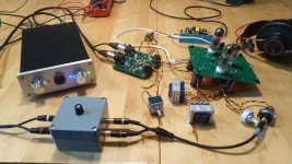
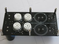
ok... no test fixture - I was too curious to test the amp. As you can see, the tubes are now on the PCB side without components, as I successfully mirrored the tube footprint 😕 Anyway, now I have no excuses why I can't put the amp in a proper housing...
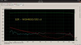
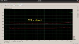
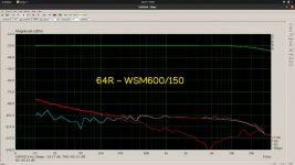
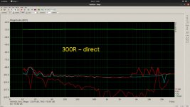
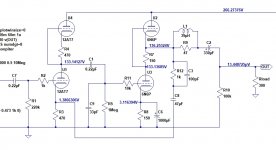
It works. No changes compared to the schematics. Honestly, it works quite nicely. No complaints about the sound from my side. It drives everything from 32R to 300R without transformer, but as you can see in the measurements, the transformer improves the THD significantly when using 32R headphones.
The spikes at "300R-direct" between 5k an 10k are some very high order harmonics; no clue if this are some measurement artefacts or interactions with the transformers. When listening, I noticed nothing in this spectral area.
The slightly higher THD at the low frequencies comes from the preamp. I used NE5532 (whyever...). This circuit with LME4562 or OPA1612/1656 gives a flat THD...
The transformers are Edcor WSM600/150.
B+ ist at 210V currently. 190V-200V should be enough, but when turning down the voltage, the power supply also decreases the heater voltage.
Measured with my audio interface, PCM1794/OPA1656/OPA1632 output, OPA1612/PCM4220 input.
Compared with the HPA in my audio interface (LME49600/OPA1656), there is almost no difference; very nice stage, wide, open, clear; punchy, fast attack, clear mids, nice high tones. It's dead silent; no hum or hiss... I am honestly surprised about the results you can obtain with this relatively simple HPA.
Next task: make a nice power supply 😀
Attachments
Look what I found on Alixpress:
6N3 + 6N6 SRPP pre amplifier board JCDQ149N, field effect tube high voltage electronic filtering / delayed power supply|Transformers| - AliExpress
But it has no direct coupling...
6N3 + 6N6 SRPP pre amplifier board JCDQ149N, field effect tube high voltage electronic filtering / delayed power supply|Transformers| - AliExpress
But it has no direct coupling...
I don't think it matters if the first stage is wired up as a quasi-SRPP or a half-mu (totem-pole) stage. Either way, the DC voltage at the output of that stage will be about half the supply voltage, minus or plus the top tube's cathode bias voltage.
What's really different is an SRPP output stage vs. a cathode follower with active load. The SRPP, if gNFB is applied, should be better, because the SRPP has gain, while the CF does not. That gain drives the NFB loop, allowing lower distortion, lower Zout, good stuff like that. Theoretically, at least.
What's really different is an SRPP output stage vs. a cathode follower with active load. The SRPP, if gNFB is applied, should be better, because the SRPP has gain, while the CF does not. That gain drives the NFB loop, allowing lower distortion, lower Zout, good stuff like that. Theoretically, at least.
Last edited:
But SRPP is largely reliant on load... Where an active loaded CF can be a "one size fits all" to an extent, the SRPP is only really good for the load it was designed for...
That's true for the first stage, which is why I called it a 'quasi-SRPP'.
The active-loaded CF ("ALCF") does work more easily over a wider range of impedances, except that for it, the higher the load Z the better, until you reach the point of diminishing returns.
The WCF, like the SRPP, is also best used into a narrow range of load R. It will work best at only one load resistance, but it will work OK over a wider range.
For the output stage, you can make the SRPP work over a small range (like 50R to 300R, or 150R to 600R) and rely on NFB to keep it linear over that range.
I'll play with the attached circuit to see how badly it falls apart when driving a non-optimal load.
Attachments
Last edited:
OK, results of simulations (not real life testing):
1) Into a 300R load, 1kHz sine wave yielding 1V rms (20mW) output, THD = 0.015% (that's good!)
2) Into a 50R load, 1V rms (20mW) load, THD = 0.23% (still OK)
If bias the 6N6P SRPP as hot as I can, to Ip = 25mA (3.25W Pdiss each triode), THD is slightly worse into both 300R and 50R.
Biasing the 6N6P SRPP cooler, I get a similar result.
I think I found the optimal spot for this particular circuit, at least in simulation.
For the output stage, you can make the SRPP work over a small range (like 50R to 300R, or 150R to 600R) and rely on NFB to keep it linear over that range.
I'll play with the attached circuit to see how badly it falls apart when driving a non-optimal load.
What if I use it as a linje stage say 10K (or 100k) when not using the headphone,will that work ok or fine?
I have a sim of a Broskie Aikido headphone amp circuit (not one of his original circuits, but a circuit that would fit into one of his Aikido 9-Pin PCBs). It's a 12AU7 totem-pole DC-coupled into a 6N6P ALCF. The THD figures are very similar to those of the previous
12AT7 totem-pole/6N6P SRPP with NFB circuit.
- The THD of both circuits is about the same, but the Aikido/ALCF does it without NFB.
- However, the ALCF/Aikido completely gives up into 32 ohms, while the SRPP with NFB soldiers on, but with higher THD (1V rms out = 0.7% THD).
The big difference is that the NFB allows the SRPP to drive 32 ohm cans, while the zero-NFB circuit clips prematurely.
--
What if I use it as a linje stage say 10K (or 100k) when not using the headphone,will that work ok or fine?
I don't know. Let's try it and see...
Simulation seems to think it will work spectacularly well. Well below 0.01% THD. However, it's a really inefficient way to get 3X gain. Two 6N6P heaters will consume 10W of electrical power, plus two 12AT7 heaters consume almost 4W, so there's 14W of power you're paying for just to light up the tubes. Then the plate supply is consuming another 14W or so.
The large electrolytic cap on the output could be a problem. I'd reduce the value of R10 to 22k or maybe 33k, to speed up the charging of C2 (the output cap). Otherwise there may be a lot of DC at the output on startup, while C2 charges up.
You could also add a pair of 15V zener diodes in anti-phase from output to ground, to prevent output voltage from going beyond 15V. That could save solid-state devices downstream and wouldn't affect performance either into headphones or a power amp.
But it looks like it could work really well as a line stage, yes.
--
Last edited:
If you use it for line, you can use 6N1 or 6CG7 instead of 6N6.
Make the output cap smaller (10uF is fine for most uses), and if you're worried about a voltage spike on power (there isn't really much of one anyway) I'd use a bidirection TVS diode instead of the zeners.
Make the output cap smaller (10uF is fine for most uses), and if you're worried about a voltage spike on power (there isn't really much of one anyway) I'd use a bidirection TVS diode instead of the zeners.
I have a sim of a Broskie Aikido headphone amp circuit (not one of his original circuits, but a circuit that would fit into one of his Aikido 9-Pin PCBs). It's a 12AU7 totem-pole DC-coupled into a 6N6P ALCF. The THD figures are very similar to those of the previous
12AT7 totem-pole/6N6P SRPP with NFB circuit.
- The THD of both circuits is about the same, but the Aikido/ALCF does it without NFB.
- However, the ALCF/Aikido completely gives up into 32 ohms, while the SRPP with NFB soldiers on, but with higher THD (1V rms out = 0.7% THD).
The big difference is that the NFB allows the SRPP to drive 32 ohm cans, while the zero-NFB circuit clips prematurely.
--
1Vrms into 32 Ohm headphone : that's more than 31mW, which is very loud and I think hardly to endure.
I try to aim at something between moderate and fairly loud levels so around 1mW to 10mW
You're completely correct. I simply chose 1V rms as a standard by which to judge the differences.
Since most headphones have a sensitivity of about 100dB for 1mW input, and converting mW to V into 32 ohms means it takes 180mV out for 1mW into 32 ohms.
If we want to measure the THD from the amp at 100dB SPL output from the 32 ohm headphones, that's 0.18V rms out to the headphones.
Going back to the sim of the Broskie Aikido headphone amp (12AU7-6N6P), the prediction for 180mV out into a 32 ohm load is for THD = 0.16% (2nd harmonic dominates; 3rd harmonic 10dB down from that). That's probably good enough, so yes, I agree with you. The Aikido headphone amp will work well enough with 32 ohm cans. Just not insanely great.
On the other hand, the SRPP with gNFB at 180mV into 32 ohms is predicted to have THD = 0.038%, still with 2nd harmonic dominating, and with no 4th or 5th harmonics present at all. That's now more truly 'hi-fi'.
Broskie does not claim the Aikido headphone amp is great at driving 32 ohm cans, only that it will work. He's completely right. However, he uses a pair of Sennheiser HD600 (if I remember correctly), which are 300 ohm impedance and will work extremely well driven by the Aikido headphone amp.
--
Last edited:
Thanks rongon for your (always) valuable response.
I am following this thread with great interest and sometimes I get the feeling that the fact that this design was originally meant for a (high impedance)headphone, : "....It's designed for higher Z headphones, but it will drive 32R without a problem as long as your headphones are loud with only 20mA of current. You can increase the current by changing 100R to 68R....."
we a little bit loosing sight of the fact that a few mW's is enough to obtain a really good sound quality.
I have build a headphone amp with a White CF output and tuned it for my Sennheiser HD650. But I am now trying to redesign it to be suitable to drive a 32 Ohm headphone.
I realized that also then few mW's is enough to produce a good sound. This makes designing a little more easier with respect to the THD.
Just my few cents of comments.
Thanks Joe.
I totally agree -- as long as your 32 ohm headphones are sensitive enough.
I say that from experience, with a pair of Fostex T50RP. Its impedance is about 60 ohms, but it is not very sensitive (I think 94dB/1mW). It needs more current (watts) to get loud, but more significantly I think, it sounds kind of sleepy without enough power driving it. So I'd say that's an exception.
On the other hand, I have a pair of Audio Technica ATH-30 that just about anything can drive and still sound good. Noticeably higher sensitivity than the Fostex cans, and lively sounding even with a wheezy amp (like my Android smartphone's headphone out).
So I guess 'it depends.'
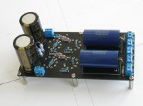
I have started building a line stage. I haven't soldered the tube sockets yet still need to use the PCB to mark the chassis for the sockets. Waiting for power supply and chassis.
Nice kit Koda, Thanks! 🙂
Nice kit Koda, Thanks! 🙂
Attachments
Last edited:
Can I use the same 12V DC/1.67A brick for the heaters? And how? Or I need a separate power supply for that?
- Home
- Amplifiers
- Tubes / Valves
- 6N3/6N6 headphone amp using PCB.