
A separate small Talema/Nuvotem toroid 2 x 7V with Graetz bridge to the 2200 µF cap (remove the 1N4001) for the filament regulator would be way beter. A 2 x 7V 3.5..5VA with secondary windings in parallel is OK. The famous Chinese BingZi 2 x 7.5V (with 220V primaries!) can also be used.
A fan has no place in good audio. Devices should reproduce music, not make noises themselves.
A fan has no place in good audio. Devices should reproduce music, not make noises themselves.
Last edited:
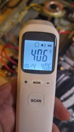
I placed a bed fan just for temperary make 7806 cool.
I have just realized that I have suitable transformer for this board. OP 8.5x0, 14.5x0x14.5. Please guide me to connect it properly. I guess I must remove FR207 near 7806 and connect 8.5vac to end of it. But how to connect 14.5 and 0 vac to?
I have just realized that I have suitable transformer for this board. OP 8.5x0, 14.5x0x14.5. Please guide me to connect it properly. I guess I must remove FR207 near 7806 and connect 8.5vac to end of it. But how to connect 14.5 and 0 vac to?
Attachments
Last edited:
Ah, I must use the Graetz bridge to feed LM7806. cannot use VAC directly to pin 1.
Is that correct that I have to disconnect pin 1 of 7806 and feed it with a new rectifier from 8.5V AC?
➡ Modification: Disconnect the 7806 input pin (pin 1) from the main rectifier and connect it to the new rectifier from 8.5V AC.
Is that correct that I have to disconnect pin 1 of 7806 and feed it with a new rectifier from 8.5V AC?
Step-by-Step Modifications:
1. 7806 Heater Supply (From 8.5V AC)
- The heater (filament) circuit originally runs from the main rectifier, which gets ~16V AC.
- Instead of using the existing bridge rectifier, you will create a new rectifier for 8.5V AC:
- Use a separate bridge rectifier (4x 1N4007 diodes or a ready-made bridge rectifier).
- Add a 2200µF/25V capacitor after rectification.
- Feed the rectified DC (~11V DC) into the 7806 regulator (pin 1).
- The 7806 will output 6V DC for the tube heaters.
➡ Modification: Disconnect the 7806 input pin (pin 1) from the main rectifier and connect it to the new rectifier from 8.5V AC.
2. High-Voltage Supply (±30V) From 14.5V-0V AC
- The original circuit uses a voltage multiplier to create ±30V DC from ~16V AC.
- You can keep this part unchanged, but now it will take power from 14.5V-0V AC instead of 16V AC.
- No modification is needed for the high-voltage section.
Final Wiring Setup:
- 8.5V-0V AC → New bridge rectifier → Smoothing capacitor (2200µF/25V) → 7806 input.
- 14.5V-0V AC → Existing rectifier and voltage multiplier (for ±30V DC).
Last edited:
JPGPT also said the voltage doubler can be omitted and a higher voltage symmetric PSU can be made. Toroids usually have 2 secondary windings.
Like a Talema 3.2VA to 5 VA 2 x 22V PCB mount toroid on a PCB with Schottky rectifiers and filter caps in CLC or CRC. Combine it with the second filament toroid on the same PCB for neater looks and less wiring. KiCad is fun!
Like a Talema 3.2VA to 5 VA 2 x 22V PCB mount toroid on a PCB with Schottky rectifiers and filter caps in CLC or CRC. Combine it with the second filament toroid on the same PCB for neater looks and less wiring. KiCad is fun!
Last edited:
My final modification is that: (I do not need to pick up the pin 1 of 7806.)
1) Remove the diode FR207 near 7806.
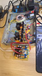
2) Transformer Output 8.5-0vac -> LT1764 Regulation board -> Out 9vdc to End point of above diode, 0v to input pin 1 of 6n3 board.
3) Transformer Ouput 14.5-0vac -> Pin 2-1 of 6n3 board. (B+/- is +38/-37 vdc)
7806 is not hot at all.
1) Remove the diode FR207 near 7806.
2) Transformer Output 8.5-0vac -> LT1764 Regulation board -> Out 9vdc to End point of above diode, 0v to input pin 1 of 6n3 board.
3) Transformer Ouput 14.5-0vac -> Pin 2-1 of 6n3 board. (B+/- is +38/-37 vdc)
7806 is not hot at all.
Hard to believe with 350 mA load current and out 16 - 6V so 10 V dropping. 10 x 0.35 = 3.5W losses to heat.
Yes that was a tip. It works as you see. It is a very good habit to adapt transformer voltages to real world demands by carefully selecting them. No penalties either unless you choose a too low voltage. Always calculate with +/- 10% mains voltage fluctuations. When the input voltage of a regulator is too low it will not regulate anymore. When it is too high it will burn energy to heat. Nothing gets better from useless heat.
Add its dropout voltage with margin to its output voltage and that should be the lowest point of ripple voltage. When tight it helps to up the filter cap value and use Schottky diodes with lower Uf like 11DQ10 or similar. With 7806 it is safe to add 2V for guaranteed working at 0.35A load current so it needs 8V absolute minimum input voltage (at mains voltage- 10%!). Normally a 2200 µF cap is used but for lower ripple in tight situations a 4700 µF may be needed. Things work out even better with an LDO regulator with for instance 0.35V dropout voltage like LT1764 you used. Avoid regulators in series.
Add its dropout voltage with margin to its output voltage and that should be the lowest point of ripple voltage. When tight it helps to up the filter cap value and use Schottky diodes with lower Uf like 11DQ10 or similar. With 7806 it is safe to add 2V for guaranteed working at 0.35A load current so it needs 8V absolute minimum input voltage (at mains voltage- 10%!). Normally a 2200 µF cap is used but for lower ripple in tight situations a 4700 µF may be needed. Things work out even better with an LDO regulator with for instance 0.35V dropout voltage like LT1764 you used. Avoid regulators in series.
Last edited:
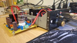
I intended to modify my preamp buffer 6n3 to increase the high voltage to about +/-95vdc by feeding it 36vac from a small transformer (5w). (I have another transformer feeding heater 6v by 7806)
I checked some changes needed as:
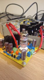
1) Replace capacitors (220uf/63v) to 220uf/200v.
2) Replace the filter caps (rated 63v (1uf, 0.01uf)) with a higher (maybe 250vdc).
Others will be kept as is:
1) Diode FR207 (rated 1000v)
2) Resistors: I used 1w/1% instead of 1/4w from beginning.
3) Transistors 2N5551 (Vceo of 160v) and 2N5401 (Vceo of 150v)
I'd appreciate comments on the above plan. Is it necessary to adjust the values of the resistors or filter capacitors?
I checked some changes needed as:
1) Replace capacitors (220uf/63v) to 220uf/200v.
2) Replace the filter caps (rated 63v (1uf, 0.01uf)) with a higher (maybe 250vdc).
Others will be kept as is:
1) Diode FR207 (rated 1000v)
2) Resistors: I used 1w/1% instead of 1/4w from beginning.
3) Transistors 2N5551 (Vceo of 160v) and 2N5401 (Vceo of 150v)
I'd appreciate comments on the above plan. Is it necessary to adjust the values of the resistors or filter capacitors?
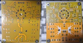
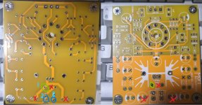
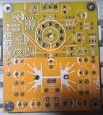
Attachments
I wonder if I must adjust resistors (Rc, Ra...) to work best with +/-95vdc. Can't find any schematics to refer to. I need to know the values of Ra, Rc.
Your guidance is highly appreciated.
Your guidance is highly appreciated.
So after chatting a lot with AI, and I found some reference schematics, then I modified to run a 6n3 tube at +/-100vdc.
I changed 2xRk from 470R to 1k, and 2 resistors from B- 12k to 34k (I used 2x68k resistors). I have no idea whether those resistor values match, but I love it.


I changed 2xRk from 470R to 1k, and 2 resistors from B- 12k to 34k (I used 2x68k resistors). I have no idea whether those resistor values match, but I love it.
Maybe ask your virtual help what he output impedance/drive capability is of your buffer. The 100V (not +/- 100V) PSU is not symmetric and not as good as the previous cap multiplier one. I think it should be regulated for best results as the circuits PSRR definitely dictates that. And what about power on/off phenomena? If a normal power amplifier is connected it may be allergic to those power on/off phenomena.
The question is what you want it to be. An inserted device just for fun or an inserted device that functions as effect generator. In either case chances are likely that the sources have far more drive capability than the buffer.
Always ask yourself what is exactly achieved or gained when inserting stuff. Then think what maybe is lost. Then think what a wire could do. A bit like asking yourself if your life will be better by having a tattoo or not 🙂
BTW please think of shielding so putting electronics in a metal casing to avoid stray in of nasty non audio signals.
Last edited:
- Home
- Amplifiers
- Tubes / Valves
- 6N3 (5670) simple tube buffer, any good?