Hi All,
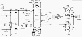
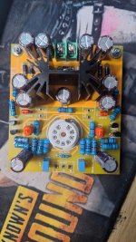
I got a 12Vac single tube (6N3) Chinese tube buffer (schematics attached).....or at least this is how the Chinese market it.
I would like to know please if it does act as a buffer (it is a unity gain circuit) so it can be used for "impedance matching".
I will bypass the input potentiometer, probably increase the input capacitors value a little and change the output capacitors for a better quality ones.
I'm using a 15Vac transformer so the DC voltage is about +/-42Vdc and not 30Vdc as in the schematics which put more "stress" on the 7805 regulator so I might also change it for a 7806 regulator.
One thing that is a bit of a mystery to me is that even when I remove the tube completely I still get very low sound output, I assume that the signal still go through the 470K and 470r to the output.
But first I would like to know your thoughts about this "buffer" as a buffer, any comment related will be appreciated.
Attachments
Even with +/- 42 volts on the tube it likely won't be operating anywhere near its linear range. So the the sound will be mushy and "tube-y". Substituting better parts on a marginal circuit would be a waste of time and money, IMHO.
When you pull the tube some signal will go through the 470K grid and 470 ohm cathode resistors.
In my opinion, these circuits were developed to make use of the likely tens, if not hundreds of thousands of 6N3 tubes still filling Chinese warehouses.
If you want a good buffer build one of the Broskie Aikido cathode followers. If you want a line stage with some gain, build one of Broskie's Aikido line stages.
S.

Thank you.
I'm after 1 tube buffer, Broskie Aikido buffers have 2.
I can use "proper" 120Vdc for the buffer that I have but I don''t know how to adjust the resistors for 120Vdc voltage, any suggestions?
I'm after 1 tube buffer, Broskie Aikido buffers have 2.
I can use "proper" 120Vdc for the buffer that I have but I don''t know how to adjust the resistors for 120Vdc voltage, any suggestions?
+/- 120 volts or just +120 volts? Probably about 200 volts minimum supply (+200 or +/-100) to get the tube to get it into a somewhat linear region. Of course you'd need to check the voltage ratings on the coupling caps if you increase the B+ voltage.
Do a search for other 5670 buffers. I think they were used on some CD players and headphone amps.
Do a search for other 5670 buffers. I think they were used on some CD players and headphone amps.
The buffer will be better at higher nominal voltages and the Cathode Follower goes from Miss Piggy to quite decent if you add CCS to the bottom.
dave
dave
That looks like a schematic that has been well thought out! Muting could be added. C14A and C14B better be 100V types. Did you design it?
SMD parts and tubes, exciting. If there is a PCB design I would build this one straight away out of curiosity.
SMD parts and tubes, exciting. If there is a PCB design I would build this one straight away out of curiosity.
Last edited:
Yes, I did.... The little tricks I've incorporated enhance open loop gain and reduce distortion. Given the warm-up time of the tube filament. why would I need to incorporate any muting?
No DC ramp up at power on? I wrote "could" and it would not hurt either. I have seen/heard quite some (tube) preamps connected to normal amplifiers having power on phenomena. Or at power off. Or both.
Did you try it with 5670?
Did you try it with 5670?
Last edited:
The filament takes its own sweet time to ramp up - why would I bother. The design hinges on the tube as boss element, and nothing can happen until the tube decides to heat up and turn on.
Why? You could up the voltages and measure a thing here and there instead of reducing hard earned money to 0 enlargening your carbon foot print at the same time.
Up the voltages, remove the 1N4001 and use a separate 6V transformer plus rectifier/cap for a 6V LDO filament regulator (or a 8..9V transformer and a 7806), use 1N4007 or similar rated diodes, use 4.7 µF MKS output caps and just try it out. Despite us armchair designers criticising the poor thing it could be exactly what you like in audio.
If you like I can send you a leftover transformer for higher B+/B-. I am cleaning out. Good so German quality NOS toroids 2 x 9V 50VA (molded) or 2 x 12V 120VA. Not pushing here as we will experience a time that transformers are nowhere to be found anymore. Calculate with 18 and 24V what results of B+/B- will be.
Last edited:
Hi Jean paul,
Thanks, you're right and I just found that I have another tranformer that can provide 150Vac and if I not wrong isabout 210Vdc after rectifier.
Any suggestion for resistors adjustment?
Thanks, you're right and I just found that I have another tranformer that can provide 150Vac and if I not wrong isabout 210Vdc after rectifier.
Any suggestion for resistors adjustment?
Not now as I have to go out now. Please note having a B+ and B-. You will have a hard time upgrading the existing B+/B- onboard cap multipliers and caps when using 150 Vac. Upgrading all these caps to 100V types did not seem very expensive to me and maybe you even have those in stock.
Law of diminishing returns, ROI etc.
Law of diminishing returns, ROI etc.
Jean-Paul -
The voltage on C14A and B is 13.6V, (or less, as there is a parallel pot with the 7.5k for adjustment), so a 25V cap will do just fine.
The voltage on C14A and B is 13.6V, (or less, as there is a parallel pot with the 7.5k for adjustment), so a 25V cap will do just fine.
@wrenchone ,
Interesting. What is the purpose of R26? Optimizing the operating conditions by adjusting the bias?
Interesting. What is the purpose of R26? Optimizing the operating conditions by adjusting the bias?
Yes - you use R26 to adjust the output voltage before the output coupling cap.. It needs a fair bit of bias, since the design is only a 5X buffer.
Pity as the design needs it (or better).I'll omit the voltage multiplier
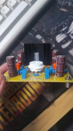
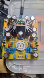
I have a quick question: Is the TO-220 42x25x25 thermal dissipation OK for operating LM7806 with the input 16vac, 350MA?
I'm wondering about two options below:
Option 1) 16vac Input -> LM7806 -> +/- 42vdc for tube.
Option 2) 16vac Input -> KA7812 -> 12vdc -> LM7806 -> +29/-27vdc for tube.
From ChatGPT, I have the calculated and answer below, but I'm unsure.
---------
Since you are using 16V AC, the rectified and filtered DC voltage is:
VDC=VAC×2−VdiodeV_{DC} = V_{AC} \times \sqrt{2} - V_{diode}VDC=VAC×2−Vdiode
Assuming a bridge rectifier with two diode drops (~1.4V total):
VDC=16V×1.414−1.4V≈21.2VV_{DC} = 16V \times 1.414 - 1.4V \approx 21.2VVDC=16V×1.414−1.4V≈21.2V
The power dissipated by the LM7806 is:
P=(Vin−Vout)×IP = (V_{in} - V_{out}) \times IP=(Vin−Vout)×I
Given:
Step 4: Heatsink Selection
To keep the LM7806 cool, you need a heatsink with thermal resistance ≤ 12.8°C/W.
Recommended Heatsinks:
If you plan for continuous operation or higher ambient temperatures, a larger heatsink (5-10°C/W) is recommended.
-------------
I understood that "Even with +/- 42 volts on the tube it likely won't be operating anywhere near its linear range.", but I want to try adding tube buffer to my Lehmann Clone headphone amp, and I want to use my existing transformer which feeds headphone amp also (IP: 0-220v; OP: 16x0x16vac x 2/0.8A).
I'm wondering about two options below:
Option 1) 16vac Input -> LM7806 -> +/- 42vdc for tube.
Option 2) 16vac Input -> KA7812 -> 12vdc -> LM7806 -> +29/-27vdc for tube.
From ChatGPT, I have the calculated and answer below, but I'm unsure.
---------
Step 1: Calculate DC Input Voltage
Since you are using 16V AC, the rectified and filtered DC voltage is:
VDC=VAC×2−VdiodeV_{DC} = V_{AC} \times \sqrt{2} - V_{diode}VDC=VAC×2−Vdiode
Assuming a bridge rectifier with two diode drops (~1.4V total):
VDC=16V×1.414−1.4V≈21.2VV_{DC} = 16V \times 1.414 - 1.4V \approx 21.2VVDC=16V×1.414−1.4V≈21.2V
Step 2: Calculate Power Dissipation
The power dissipated by the LM7806 is:
P=(Vin−Vout)×IP = (V_{in} - V_{out}) \times IP=(Vin−Vout)×I
Given:
- Vin≈21.2VV_{in} \approx 21.2VVin≈21.2V
- Vout=6VV_{out} = 6VVout=6V
- I=0.35AI = 0.35AI=0.35A
Step 4: Heatsink Selection
To keep the LM7806 cool, you need a heatsink with thermal resistance ≤ 12.8°C/W.
Recommended Heatsinks:
- Medium-sized aluminum heatsink (~10-12°C/W)
- Clip-on TO-220 heatsink (~10°C/W)
- Larger finned heatsink (5-10°C/W) for better cooling
- Mounting on a metal chassis for better heat dissipation
If you plan for continuous operation or higher ambient temperatures, a larger heatsink (5-10°C/W) is recommended.
-------------
I understood that "Even with +/- 42 volts on the tube it likely won't be operating anywhere near its linear range.", but I want to try adding tube buffer to my Lehmann Clone headphone amp, and I want to use my existing transformer which feeds headphone amp also (IP: 0-220v; OP: 16x0x16vac x 2/0.8A).
Attachments
-
 z6439390627179_70b46166d2e202f42149c6dfe635abb9.jpg229 KB · Views: 30
 -
 z6439390627882_7879446e2afa8c25023a1609721cffa1.jpg454.8 KB · Views: 26
 -
 z6439390640185_966966451673759c1c0f0473be691d0c.jpg386.2 KB · Views: 31
 -
 z6439390663349_cee590661e568c10a6daade0ba372552.jpg298.6 KB · Views: 28
 -
 z6439390668978_4f3a66ccde4edce57c1e71a62cc128bf.jpg446.3 KB · Views: 26
 -
 z6439390673340_66bb06fbdff646ee7c17e7615a2bd114.jpg234.2 KB · Views: 26
 -
 z6439390692690_dc6ea6043486024a9d7f7447130a943b.jpg321.4 KB · Views: 30
- Home
- Amplifiers
- Tubes / Valves
- 6N3 (5670) simple tube buffer, any good?