Hi guys!
I built this preamp with a 6N1P from a Svetlana Technote. It works well and sounds great. However, it seems that there is too much gain that I can't open my 100K pot. The most is up to 8'oclock only.
1. What formula can I use to determine the gain?
2. Must I increase/decrease the resistance of the plate resistor?
3. What Happens if I increase/decrease the value of the 100uf capacitor?
Thanks for the help!
JojoD
Attachments
Get rid of the 100uF cap, this will lower distortion, and gain. Also a larger value pot could be used, again lower distortion, and more signal impedence. Might try lowering B+ voltage.
Ok, so is it true then that when I increase the 100uf cap, gain also increases? And when I decrease it's value (or remove it), gain also decreases?
Ok, so is it true then that when I increase the 100uf cap, gain also increases? And when I decrease it's value (or remove it), gain also decreases?
Not true. Changing the value changes the gain only for low frequencies.
Changing the value of the 100u capacitor doesn't change the gain but the frequency at which it takes effect. The capacitor is a short circuit at AC and prevents an AC signal appearing at the cathode that would cause negative feedback (reducing gain). You can calculate the gain of stage (without feedback) using:
G = uRL/(RL+ra)
Where:
u = the amplification factor of the valve
RL= the anode load resistor
rl = the anode resistance of the valve at the operating point
I don't have data for the 6N1P to hand, but it should be on your technical note.
Removing the 100u capacitor will reduce gain, but greatly increase output capacitance, making the stage incapable of driving cable capacitance. By the sound of things, you have so much gain that you could afford to convert your stage into a cathode follower. This is easily done.
Leave the cathode resistor where it is, but lift the lower end away from 0V. Remove the anode resistor entirely, and connect it between the lower end of the cathode resistor and 0V. Remove all connections to the grid, and connect a 10k resistor as close as possible. Connect a 1M resistor to the other end of the 10k resistor and between the junction of the two resistors coming from the cathode. Connect the anode directly to HT. You now have a self-biased cathode follower, but need to make signal connections. Add a 10n 400V capacitor between the wiper of your volume control and the junction between the 10k and 1M resistors. Move your output coupling capacitor to connect to the cathode. Enjoy the results...
Hello, arnoldc. Your equation isn't quite right because the inversion of the valve means that you see Rk multiplied by a factor of (u+1). That's why you see the (u+1) factor is so many equations such as for Miller capacitance. Thus, your equation should be:
gain = u/(1 + [(rp + Rk(u+1)) / Rl])
Which is perhaps not too elegant, so this might be better:
gain = uRL/[RL + ra + Rk(u+1)]
Either way, with typical values of u, neglecting the +1 factor only contributes a small eror.
As you say, a cathode follower has a gain of (almost) unity.
The diagram's rather nasty, but you can now see how a common cathode stage can be converted into a cathode follower.
Attachments

EC8010 said:Hello, arnoldc. Your equation isn't quite right because the inversion of the valve means that you see Rk multiplied by a factor of (u+1). That's why you see the (u+1) factor is so many equations such as for Miller capacitance. Thus, your equation should be:
gain = u/(1 + [(rp + Rk(u+1)) / Rl])
Which is perhaps not too elegant, so this might be better:
gain = uRL/[RL + ra + Rk(u+1)]
Either way, with typical values of u, neglecting the +1 factor only contributes a small eror.
As you say, a cathode follower has a gain of (almost) unity.
The diagram's rather nasty, but you can now see how a common cathode stage can be converted into a cathode follower.
Thank you very much for the schematic! The 6N1P Datasheet says Anode resistance is 4400 ohms (nominal), and u = 33, when I use it to your formula I get gain of 20. Am I on the right path?
Thank you for your patience,
JojoD
JojoD818 said:The 6N1P Datasheet says Anode resistance is 4400 ohms (nominal), and u = 33, when I use it to your formula I get gain of 20.
That's right, removing the cathode resistor will drop the gain to 20. Actually, it will probably be a little less because valve manufacturers always quote ra at maximum current and a low anode voltage, which gives a lower figure than you usually obtain in practice. But if you are only able to turn your volume control to 8 o'clock, this drop in gain will be almost unnoticeable. I really think you ought to try configuring the stage as a cathode follower...
The 6N1P Datasheet says Anode resistance is 4400 ohms (nominal), and u = 33, when I use it to your formula I get gain of 20. Am I on the right path?
I added the tube to Tube Cad.
It got a gain of 17 unpypassed and a gain of 29 bypassed, or 24.6 dB vs 29.3 dB. The Cap adds about 5 dB to the gain.
The other thing that changed was the output Z.
It went from 4 k with the cathode bypacss cap to 15k unbypassed. Along with a calculated current of 1.9 mA, this circuit would not be a candidate for driving long or highly capative loads.
By the way, Tube cad recomended a 70 uF Bypass, so the 100 uF
seems realistic.
HTH
Doug
Hi,
Assuming you looked at the Svetlana datasheet the nominal Ri is NOT 4k4 but 11K for the 6N1P.
Cheers,😉
The 6N1P Datasheet says Anode resistance is 4400 ohms (nominal), and u = 33, when I use it to your formula I get gain of 20. Am I on the right path?
Assuming you looked at the Svetlana datasheet the nominal Ri is NOT 4k4 but 11K for the 6N1P.
Cheers,😉
Attachments

EC8010, i posted the formula from the article of Gordon Rankin which i mis-typed 
it should have been
gain (unbypassed) = mu*(1/((Rp+mu*Rk)/Rl))
for a grounded cathode circuit as originally posted i guess...
if you put in the circuit to tube cad using textbook cathode follower the gain is (0.93 or -0.648dB)
it should have been
gain (unbypassed) = mu*(1/((Rp+mu*Rk)/Rl))
for a grounded cathode circuit as originally posted i guess...
if you put in the circuit to tube cad using textbook cathode follower the gain is (0.93 or -0.648dB)
fdegrove,
Thanks for the info, it did say "Plate Resistance (Nominal) = 4,400 ohms" and there is no other item about plate/anode resistance on the Svetlana Datasheet. Thanks for telling me.
EC8010,
I'm lost with the formulas, I mean, which applies to what.
For common cathode: gain = uRL/[RL + ra + Rk(u+1)]
For cathode follower: gain (unbypassed) = mu*(1/((Rp+mu*Rk)/Rl))
Are these correct?
JojoD
sorry, that formula, which came from the bugle 45 article could be wrong. just use UC8010's version. but, this is the formula that was in gordon rankin's 807 amplifier article:
gain (unbypassed) = u/(1 + [(rp + Rk x u) / Rl])
gain (unbypassed) = u/(1 + [(rp + Rk x u) / Rl])
QUOTE]Assuming you looked at the Svetlana datasheet the nominal Ri is NOT 4k4 but 11K for the 6N1P[/QUOTE]
Link to 6N1P datasheet
The Datasheet says 4400 ohm. Your link does say 11k.
Interesting.
Another Refrence
And a third
Seems there is a bit of confusion on values.
🙄
Cheers.
Doug
Link to 6N1P datasheet
The Datasheet says 4400 ohm. Your link does say 11k.
Interesting.
Another Refrence
And a third
Seems there is a bit of confusion on values.
🙄
Cheers.
Doug
DougL said:QUOTE]Assuming you looked at the Svetlana datasheet the nominal Ri is NOT 4k4 but 11K for the 6N1P
Link to 6N1P datasheet
The Datasheet says 4400 ohm. Your link does say 11k.
Interesting.
Another Refrence
And a third
Seems there is a bit of confusion on values.
🙄
Cheers.
Doug [/QUOTE]
Both other reference seems to say its 600 ohms? Mine is a Sovtek, maybe I should find a Sovetek datasheet. 🙄
Is there a way to measure it as per tube?
JojoD
Hi,
That 600 Ohm is a cathode resistor.
Here's a another Russian datasheet:
IN CYRILLIC....
Note that Ri is a dynamic value. Still unless the Svetlana 6N1-P is a totally different tube, which it is NOT, I fail to see how Ri can approach 4K4 under any operating conditions.
Cheers,😉
Both other reference seems to say its 600 ohms? Mine is a Sovtek, maybe I should find a Sovetek datasheet.
That 600 Ohm is a cathode resistor.
Here's a another Russian datasheet:
IN CYRILLIC....
Note that Ri is a dynamic value. Still unless the Svetlana 6N1-P is a totally different tube, which it is NOT, I fail to see how Ri can approach 4K4 under any operating conditions.
Cheers,😉
Frank, EC8010, guys...
Since this is for my tube research, i want to understand what is meant by Heater to Cathode Voltage (100V for 6N1P)?
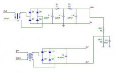
Attached is a basic psu experiment with HT=280V and heaters at 6V. Is the combination of R4, R5 what is called a ground lift? If R4 and 5 have the same value, their junction would be at 140V right?
Let's say that the measured cathode voltage of my circuit is at 120V, then the cathode-heater diff is 114V right? If I connect the ground of my heaters to the junction of R4 and 5 then my tubes are safe since my heaters will be referenced at 140V, correct?
Am I understanding things correctly? Please, a moment of your time would be greatly appreciated.
JojoD
Since this is for my tube research, i want to understand what is meant by Heater to Cathode Voltage (100V for 6N1P)?
Attached is a basic psu experiment with HT=280V and heaters at 6V. Is the combination of R4, R5 what is called a ground lift? If R4 and 5 have the same value, their junction would be at 140V right?
Let's say that the measured cathode voltage of my circuit is at 120V, then the cathode-heater diff is 114V right? If I connect the ground of my heaters to the junction of R4 and 5 then my tubes are safe since my heaters will be referenced at 140V, correct?
Am I understanding things correctly? Please, a moment of your time would be greatly appreciated.
JojoD
Attachments
Reading the curves of Svetlana's and the cyrillic, minimum Rp seems to be around 5.9-6.2k. (Above the curvy part).
4.4k seems to be a bit optimistic 😉
4.4k seems to be a bit optimistic 😉
Hi,
You're doing fine.
THEORY.
Cheers,😉
Am I understanding things correctly? Please, a moment of your time would be greatly appreciated.
You're doing fine.
THEORY.
Cheers,😉
- Status
- Not open for further replies.
- Home
- Amplifiers
- Tubes / Valves
- 6N1P preamp too much gain...