
Last weekend a view friends came over to my place to do a listening test.
I had lower the amplification factor of the tube buffer to 1x with a resistor at the input and used a switch to bypass the tubebuffer with a noemal signal wire.
Nobody could tell the difference between the tubebuffer or the signal wire.
This was a confirmation for me what i had notised before. This tubebuffer ad no coloration to the signal.
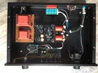
Attachments
Hello,
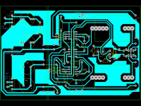
i would like to try to do this buffer...wanna ask you, if the picture of PCB traces on you .pdf is mirorred, so i mean look from above? Thanks
i would like to try to do this buffer...wanna ask you, if the picture of PCB traces on you .pdf is mirorred, so i mean look from above? Thanks
Nice little project, seen that schematic somewhere before...errors and all.
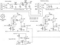
From my experience messing with this type of tube (6S6B = half 6N16B) I found that in reality the optimum THD result is obtained with anode voltages quite different to what you claim (Koifarm).
In fact, with B+ over 250V (as long as anode volts in quiescent state are within datasheet limiting values), and also with Ia in the region of 4-6mA.
I.e. even with anode as low as 50V, but B+ supply up to 300V. It all depends on the anode load.
Hello,
i would like to try to do this buffer...wanna ask you, if the picture of PCB traces on you .pdf is mirorred, so i mean look from above? Thanks
Yes, they are mirrored. So you can use the toner transfer method to make a PCB.
Nice little project, seen that schematic somewhere before...errors and all.
From my experience messing with this type of tube (6S6B = half 6N16B) I found that in reality the optimum THD result is obtained with anode voltages quite different to what you claim (Koifarm).
In fact, with B+ over 250V (as long as anode volts in quiescent state are within datasheet limiting values), and also with Ia in the region of 4-6mA.
I.e. even with anode as low as 50V, but B+ supply up to 300V. It all depends on the anode load.
Your right, with 10k load and 1V output the B+ of 140v is good for low distorsion. When you need 10v output and/or low load you need to change the resistors and/or B+.
Last weekend a view friends came over to my place to do a listening test.
I had lower the amplification factor of the tube buffer to 1x with a resistor at the input and used a switch to bypass the tubebuffer with a noemal signal wire.
Nobody could tell the difference between the tubebuffer or the signal wire.
This was a confirmation for me what i had notised before. This tubebuffer ad no coloration to the signal.
It means that you cant hear tube coloration sound?!

Do I want it then ?! 😎
I would expect tubish sound from tubes 🙄

Any Gerber file to share?Some lost pictures and schematic.
thanks...
- Status
- Not open for further replies.
- Home
- Amplifiers
- Tubes / Valves
- 6N16 12x preamp srpp/cathode follower with printed circuit board design.