How much do you expect to have output power? I am afraid you will be not happy when you find out that it is less than 1 Watt and with high distortion.
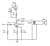
Really? if I use the transformer and tubes in parallel as the load I get 6W sine drive out of it. Was hoping for at least that, but cleaner, and without the need for transformer current balance. Right now I'm using this circuit. I was just thinking of rearranging it. I know I drew it as single rather than parallel. I was just going to halve the Ra-a.
Attachments
Last edited:
Agree, ~~1 Watt.
The top tube tries (and fails) to work Constant Current. This is at-best 25% efficient, instead of the 50% possible with ideal push-pull.
Taking the load above the top cathode resistor makes it respond to load current. Review Broskie's "SRPP" essays. At very best it becomes push-pull. But the load is critical. (At high Z load it degenerates to push-push.)
The circuit as shown has DC balance, but not AC balance. It is merely SE with a weak active load.
I'm thinking series instead of parallel to make balancing easier? Thoughts and critique welcome!
The output must be connected on the cathode of the upper tube. Otherwise it is no AF signal at the grid, and upper tube is just a passive load without any contribution to the output power, i.e. poor efficiency and possible 2nd harmonic distorsion even at low level. Care must taken for correct DC balance, too. And also you have to verify that cathode-filament isolation can sustain booth DC and AC voltage... Eventually use two distinct tubes with separate heather windings.
Also, R2 must be equal to R1 = 1k otherwise some problem at higher frequencies...
Last edited:
Thanks for the comments. The VhkMAX is +-300V so at least that's ok.
I guess I'll do a little more reading. I use an Aikido style circuit for headphones which Broskie tells me operates in PP and so I was attempting to adapt it to the 6N13S. I'll also read up on Philips implementation of SRPP in some of their radios.
I guess I'll do a little more reading. I use an Aikido style circuit for headphones which Broskie tells me operates in PP and so I was attempting to adapt it to the 6N13S. I'll also read up on Philips implementation of SRPP in some of their radios.
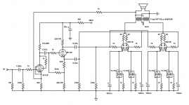
The Philips circuit is also found in this data sheet. As stated, you need to move your output connection. All of these circuits that I have come across have used pentodes, I have never tried a triode, but I have used a mosfet for the top tube.
In either case DC balance is determined by the matching of the tubes. You can adjust this a bit by tweaking the value of the cathode resistor in the bottom tube.
The top grid stopper must be a low value (like 1K) as it passes signal and will form a low pass filter against the Miller capacitance of the top tube. This circuit does not show a resistor on the bottom tube, but a 1K can be used here too, between the 470K and the tube.
If using pentodes, there IS a connection between the 8 uF screen bypass on the top tube and the cathode of the same tube. This circuit was commonly used with 6CW5 pentodes and its series string heater variants like the 45B5 / UL84, and ran off rectified 230 volts in European radios driving 600 to 800 ohm speakers.
Attachments
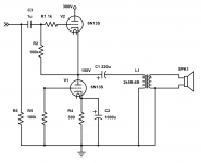
Ok. I feel like I must have been on glue last night. I drew an SRPP output with the output attached to the bottom plate instead of the top cathode.
What I meant to do was an Aikido-esque circuit, but I drew it upside down haha
Thanks again for suggestions.
What I meant to do was an Aikido-esque circuit, but I drew it upside down haha
Thanks again for suggestions.
Attachments
Last edited:
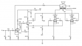
Flemming Madsen on Iceland has made a parafeed SRPP with 6AS7/6N13P that he states is giving about 5 W out.
http://www.fva.is/~flemming/hsakram/int-srpp-amp/SRPP-grein-spmagasine.pdf
http://www.fva.is/~flemming/hsakram/int-srpp-amp/SRPP-grein-spmagasine.pdf
Attachments
 Thread reopened, requested post deleted.
Turner Audio has a great write up. It talks about how OTL might actually be better with an OPT or SMT (Speaker matching transformer) as he calls some of them.
He describes a 6AS7 (both sections paralleled) output that is purported to produce 25W (class B) at an idle of 30ma with 150B+ into ~750 ohms. 6N13S is NOT a 6AS7. Ri for 6AS7 = ~280R, Ri for 6N13S is ~460R (per plate).
Right now I have the amp biased at 75ma/150V per section. I get 6W sinewave drive. Music is noticeably more than 6W though, at least before i hear the distortion. It's still not clipping.
See figure 6
OTL-amps-pros-cons
Attachments

Last edited:
6N13S is NOT a 6AS7. Ri for 6AS7 = ~280R, Ri for 6N13S is ~460R (per plate).
Where this information is from ?
From the 6N13S datasheet: "ВНутреннее сопl~отивление каждого триода не более 460 0м"
Translated: "internal resistance of each triode is not more than 460 0hms".
Translated: "internal resistance of each triode is not more than 460 0hms".
Rp depends on the plate current. Are the operating points the same ?
According to the data sheets:
6AS7 at Ug = -20 V and -40 V and Ia = 120 mA ; µ = 2.0
6N13S at same operating points; µ = 1.9
6AS7 at Ua = 90 V, Ug = -20 V and -40 V; gm = 6.15 mA/V ----> Rp = 325 ohms
6N13S at same operating points; gm = 5.9 mA/V ----> Rp = 322 ohms
So nothing have changed so far. These tubes are equal as have been assumed for few decades.
Last edited:
Well the 6AS7 run far hotter than the 6N13S, and the grid wire spacing is closer on the 6AS7. I agree they are closer than a 6N1P and a 6DJ8 though.
Turner Audio has a great write up. It talks about how OTL might actually be better with an OPT or SMT (Speaker matching transformer) as he calls some of them.
Turner also said the following at the top of the page:
"In my humble opinion, all tubed OTL amps are flawed because the tubes used operate in their most non linear and least efficient manner and are very prone to overheating."
😉
- Status
- Not open for further replies.
- Home
- Amplifiers
- Tubes / Valves
- 6N13S output stage. Thoughts?