wg_ski & smoking-amp,
Thanks for repeating some of the things I have said many times. And you give a better explanation too.
High frequency harmonics of the fast rise large transient currents are a characteristic of a capacitor input filter.
And those capacitor input filters create a very powerful and very noisy ground loop. Keep all the [loop] wiring of the secondary, ss diodes / tube rectifiers, and first capacitor Very short (as local of a loop as possible, not only for the voltage drop in the wiring, but the magnetic loop of a single turn large transient current.
Given the ground loop, I use choke input filters whenever possible. And, the power transformer runs much cooler with average secondary current of a choke input filter, versus the very large I-Squared x DCR transient current of a cap input filter.
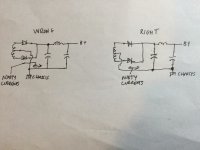
You get rid of the ground loop by connecting the negative terminal of the last cap to star ground/chassis. And only connect it there. Do not run the current that flows on the first capacitor (with all the ripple and harmonics) through that wire that connects between the second cap and the chassis.
Attachments
Absolutely,
Said that often too.
For other ground loop examples, consider a 2 stage single ended amplifier.
Make local ground loops of:
Input tube circuit: RCA input connector; grid return resistor; self bias resistor and bypass cap; and then return the bypass cap to the center ground/chassis (and do not ground the RCA return to the center ground/chassis; use insulating washers).
Output tube circuit: grid return resistor; self bias resistor and bypass cap; and then return the bypass cap to the center ground/chassis.
I hope you can visualize these local ground loops, that you then connect to the central ground/chassis.
Be sure to connect the common Tap of the output transformer secondary to the central ground/chassis.
If you have a 3 wire outlet and 3 wire IEC power cord, connect the IEC connector ground lead to the center ground/chassis.
Safety First!
Prevent the "Surviving Spouse Syndrome".
Just my opinions
Thanks for all the guidance.
I am progressing with the construction slowly.
I will get a couple of Hammond mains transformers that have slightly better voltages.
460 vac/650 vdc is a bit much to "burn" away
I am progressing with the construction slowly.
I will get a couple of Hammond mains transformers that have slightly better voltages.
460 vac/650 vdc is a bit much to "burn" away
As yet stated, the most efficient and economic way to »burn« surplus voltage is a choke input filter. Please judge by yourself what fits you better.
Best regards!
Best regards!
Yes, that's why I have 6 tubes.With a Hammond 1650T OPT at 1.9K Ohms. Gonna take at least a parallel pair of 6L6GC on each P-P side, or switch to some big TV Sweep tubes.