Hello
I have 6 pieces of 6l6gc tube and 1 Hammond 1650T OPT, and I am looking for a simple wiring diagram for a PP monoblock,
I have found some schematics at Turner-audio.au but they are a bit too advanced. Anyone have any good suggestions
Regards Peo
I have 6 pieces of 6l6gc tube and 1 Hammond 1650T OPT, and I am looking for a simple wiring diagram for a PP monoblock,
I have found some schematics at Turner-audio.au but they are a bit too advanced. Anyone have any good suggestions
Regards Peo

The 1650T is not very suitable for a couple of 6L6GCs, very low 1.9K primary impedance. It's also a 120W OPT, you can use a parallel push-pull arrangement, 3 tubes per channel.
With a Hammond 1650T OPT at 1.9K Ohms. Gonna take at least a parallel pair of 6L6GC on each P-P side, or switch to some big TV Sweep tubes.I have 6 pieces of 6l6gc tube and 1 Hammond 1650T OPT
It´s for Hi-Fi
https://www.hammfg.com/electronics/transformers/classic/1608-1650?referer=790
something like this
https://www.hammfg.com/electronics/transformers/classic/1608-1650?referer=790
something like this
Attachments
Ketjie,
That is a very interesting simple push pull amplifier.
I especially like that 6V6 concertina with the two 10k resistors.
(and I do not really like almost all concertinas).
That dominant pole, the series 270k pentode load, 100pF cap, and 20k to ground is also interesting. It is at about 5.5kHz.
OK, the frequency is a very little higher than that, because of the 6SJ7's parallel plate impedance, rp.
However, the B+ documentation does need some work, to make it correct.
400VCT and a 5U4G rectifier does not put out 440V B+.
200Vrms x (Root(2)) = 283V peak, and then there is the voltage drop through the 5U4G.
Last edited:
The post #6 schematic is most likely running with those mu follower drivers for high power output with 450V B+.
The output tubes don't have individual bias controls nor current measuring (or distributing) cathode resistors. That design will need matched tubes to distribute the plate currents evenly. And periodic tube removal to monitor long term current matching. Measuring idle current across the plate resisters is not recommended, unsafe. Also, even matched tubes don't guarantee even current distribution at all current levels (needs unbypassed individual cathode resisters).
It presumably has the plate resistors on the outputs to avoid parasitic oscillation between the tubes, but you will want a HF oscilloscope (and individual cathode resisters to measure currents) to verify that is working for each set of tubes used. This doesn't really qualify as "simple".
Do you have matched 6L6GC tubes? Do the mu follower tubes have sufficient heater cathode V rating to handle maximum drive signals? Do you have a high frequency capable Oscilloscope?
A single pair of 30+ Watt TV Sweep tubes might be a better fit and lower cost. (42KN6 , 26LX6, 36LW6, 6KG6, EL509, 6P45S ... ) They can handle the current for the 1900 Ohm OT. (can run in class AB1 for full OT power output )
Last edited:
The BIGGEST sweep tubes aren’t necessarily linear at quiescent currents you would probably run an amp like this at. More moderate sized ones cost less and may result in more hi-fi sound. I like *DQ5 and 6CB5. They kind of look like 6550’s if you run the screen around 125V. 21LG6 another good one. Less expensive and easier to source multiples, too. Two CB5’s are cheaper than a single LW6, even if you count the sockets and top caps. I have been playing with the biggest ones, getting prepared for when a build a kilowatter. But in the meantime I’ve found those 26DQ5’s to sound VERY nice at practical power levels. I may build a tweeter amp out of some (2” CDs, of course).
A lot of the 17-18 watt compactron sweeps with 1.2A heaters would work well in quads, or pairs if you only want 40-50 watts. Linear at the currents you’ll be using and cheap as hell. Also available without top caps (6JN6, etc). Think of them as poor man’s (or Russia-boycotting) EL34’s. If you run the screens at 150 instead of 400, of course.
A lot of the 17-18 watt compactron sweeps with 1.2A heaters would work well in quads, or pairs if you only want 40-50 watts. Linear at the currents you’ll be using and cheap as hell. Also available without top caps (6JN6, etc). Think of them as poor man’s (or Russia-boycotting) EL34’s. If you run the screens at 150 instead of 400, of course.
I find one pair of triode strapped sweep tubes will work into 1k9 nicely on 320V B+ Generally, the higher the heater current, the higher the peak cathode current available.
If you parallel 3 pairs of 6L6 strapped as triodes, you should get about the same power as one pair of triode strapped sweeps based on the peak cathode current ratings.
If you parallel 3 pairs of 6L6 strapped as triodes, you should get about the same power as one pair of triode strapped sweeps based on the peak cathode current ratings.
Triode strapped at 100 to 150 mA, right? A liiiitle steep for 500-600 volt operation, and still damn hot at 450. The slightly smaller ones are happy under 50 mA, even without a **** ton of global NFB.
Triode strapped, 65mA or so, 320V B+ for ~20W Pd but it really depends on the tubes. I use 320V B+ because it happens to be 120V into a Delon doubler and so the PT is cheap.
I'm running one amp at 30mA using 12AV5GA and it's great. I'm running one at 60mA with 12GT5, and I'm running 100mA - 120mA with 6P45S. Also 80mA with 6P36S.
The 12* amps are running with 1k4:4R ratio, the 6* amps are running 650R:4R. The ratios can also be set for 2k5:4R and 6k:4R.
The calculator at VTADIY shows this for the load line for the 1k4 output version.
It looks like a very bad match but it isn't - the Pd is higher than stated on the datasheet for audio.
Last edited:
If you want triode, you just need a pair of these to drive 1900 Ohm. Maybe even a single bottle 6528A or 6336A would work (being dual triodes).

Last edited:
$24 here:
https://www.ebay.com/itm/2251132758...fpGVjffnT84tDOMYmvPoMvTd4=|tkp:Bk9SR6yb8b79YA
Well, those 6BQ6GTB do have caps to tie a string on, so you can use them for fishing bobbers after they burn out. 😎😉🙂
https://www.ebay.com/itm/2251132758...fpGVjffnT84tDOMYmvPoMvTd4=|tkp:Bk9SR6yb8b79YA
Well, those 6BQ6GTB do have caps to tie a string on, so you can use them for fishing bobbers after they burn out. 😎😉🙂
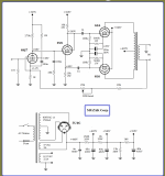
There is a simple Amp using the Hammond 1650T OT and two 42KN6 tubes, with two 6FY7 , 4 tubes total, from Glass Audio 3/1995 pg. 18
It's actually a Williamson type design with local Fdbks, so should be low distortion.
It's actually a Williamson type design with local Fdbks, so should be low distortion.
Last edited:
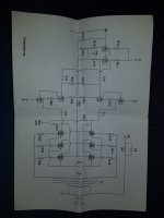
Here is the 1st page schematic from Glass Audio 3/95 pg 18. Check Glass Audio for the whole article.
Whether or not using this schematic, the snubber network could be useful for the Hammond 1650T OT in other schematics. (the final square wave overshoot with the snubbers here was less than 1%)
I would consider possibly moving the 300K local Fdbks to the UL taps, along with the RC snubbers. Since the UL winding is usually more closely coupled to the secondary than the plate taps.
Readjust the R values for the 40% reduced voltage at the UL taps.. The high impedance plates can drive right thru Xfmr leakage L (out at the plate taps, where it is worst) transparently then. It would need some checking for stability due to possible phase shift at the UL taps. If unstable, then a tiny cap from points A and B to the respective V1, V2 plates could restore HF phase alignment.
A set of 6HJ5 tubes could replace the 42KN6 tubes to go cap-less. (If you can still find them, they were very popular in Pete Millett's Engineers monoblock Amp.) Or 3x 6L6GC parallel.
This could be like a "poor mans" Citation II then. Williamson with local Fdbks.
Last edited:
The 6HJ5 tubes would be more optimal with a 2.5k, 2.7K or 3.3K P-P OT. They are rated 280 mA DC versus 400 mA DC for the 42KN6s.
(6L6GC are rated around 110 mA DC )
(6L6GC are rated around 110 mA DC )
Last edited:
Unless you're making a hot class A amp, the average current isn't as important as peak current IMHO.
6BQ6GB is only rated for 110mA also, but 400mA peak.
Also, for whatever I have been calculating based on 6L6, not the GC version. This gives you another 10 watts per tube but no additional peak current so I think the power output would be similar.
6BQ6GB is only rated for 110mA also, but 400mA peak.
Also, for whatever I have been calculating based on 6L6, not the GC version. This gives you another 10 watts per tube but no additional peak current so I think the power output would be similar.
Yes, agreed. The GE handbook gives avg DC rating, but not the peak rating, but is quick to find. Have to look on the actual datasheets to get the peak rating. But usually the peak rating is around 3.5x the avg rating. Not always though for some oddball tubes or pulsed ones.
Some peak current ratings:
6LW6 1400 mA
26LX6 1400 mA
6CB5A 770 mA
6LG6A 1100 mA
6HJ5 1000 mA
6KV6A 950 mA
21HB5A 800 mA
6LR6 1300 mA
6L6GC/7027 no data, but should be around 400 mA
6KG6/EL509/6P45S only gives 500 mA avg, which should translate to 1750 mA peak, but I doubt it, only a 2 Amp Htr
Some peak current ratings:
6LW6 1400 mA
26LX6 1400 mA
6CB5A 770 mA
6LG6A 1100 mA
6HJ5 1000 mA
6KV6A 950 mA
21HB5A 800 mA
6LR6 1300 mA
6L6GC/7027 no data, but should be around 400 mA
6KG6/EL509/6P45S only gives 500 mA avg, which should translate to 1750 mA peak, but I doubt it, only a 2 Amp Htr
Last edited:
- Home
- Amplifiers
- Tubes / Valves
- 6L6GC Monoblock schematic