Ok, I really don't know. Here is an excerpt (I saw on the Steel Guitar Forum) from a correspondence between the builder, Jim Evans and another amp builder, Ken Fox:
"The next item that would merit my concern is regulating the screen voltage of the output tubes. This is far more important that regulating the plate voltage by some "super-designed" high-voltage main-supply. If you hold the screen-grid voltage constant in the output tubes, you can get away with all kind of "sags" in the main DC supply to the plates. In fact RCA engineers learned that it would take more than ten times the regulation of the main supply (lots of weight in the power transformer core, heavier windings, and much larger filter capacitance) to match simply regulating the screen-grid voltage. The technique I used for this came from a friend and master-engineer (Al Hart) in Chicago, who designed all the "Grommes" and "Precision: amps in the early Hi-Fi revolution. This was simply an "emitter follower regulator" which for convenience and affordable performance was a standard (inexpensive at the time) glass 6L6.
Interestingly Robert Crooks likewise regulated the screen voltage for the (TV horizontal sweep) tubes he used for audio outputs. But since these required only a regulated +150 VDC he used the same gas tube regulator as was used in tube TV circuitry. He and I not only exchanged some ideas, but in 1960 when I worked in Dallas in Industrial Electronics, I bacame his area service-rep, and repaired Standel amps for his Dallas dealer.
One more approach I used in the Compactra-100 ,for output balance, was the "DC-Balance" I picked up this technology from the upper-end Hi-Fi amps, built by Fisher.
The same argument can be presented here as for the AC-Balance: Instead of expensive precision resistors, simply use an inexpensive trimpot to balance the plate current of the two output tubes. "
So the idea was to keep it clean-no sag distortion. This was also designed in the early to mid 60s. So maybe some experimentation is in order or I can just use what has worked for almost sixty years. Regardless, it's been educational. Thanks
Well, nothing is simple, particularly when adding newer electronic technology to an older piece of gear. I did a lot of research over the weekend and, while I am no subject matter expert, I know a lot more about capacitance multipliers and voltage regulators. There are problems to deal with when adding SS devices that start up instantly to a sixty-year-old tube amp. Likewise, more protective components are needed to keep a circuit from self-destructing should things go wrong. So, the easiest and cheapest solution is to get a small transformer for the 6L6 heater and keep using it. While not the ideal design, it’s worked for almost sixty years. This will also allow me to get the amp refurbished, improved and working (hopefully) reliably. Building a capacitance multiplier / voltage regulator on an octal base sounds good but can maybe be built up later. It would add peace of mind concerning reliability. A Maida circuit probably provides superior audio quality and may be good for another project.
Oh, and by the way, we tend to think that we carry around all the answers to everything in our pockets. Hey Siri. But I wasted a lot of time searching the net for info. I did find some good stuff, but all the info I needed was found in the pages of a couple of books sitting on the end table the whole time. Thanks Merlin.
Cheers all
Yes, this is the reason to regulate the screens. It makes the amp more linear. Subjectively it makes the amp sound more powerful. Once I started regulating the screens, I never went back. In this amp, I think the the 6L6 is the active device in a capacitor multiplier. It is not really regulated (even though it says "regulated" on the schematic). A tube is going to be much more rugged and forgiving than solid state, especially for a guitar amp. I have personally not blown a Maida regulator in my amps. Start up is not a problem. The voltage ramps up and the regulator stops at the desired voltage. I think Barf has a sound plan. I hope you post follow-up.Ok, I really don't know. Here is an excerpt (I saw on the Steel Guitar Forum) from a correspondence between the builder, Jim Evans and another amp builder, Ken Fox:
"The next item that would merit my concern is regulating the screen voltage of the output tubes. This is far more important that regulating the plate voltage by some "super-designed" high-voltage main-supply. If you hold the screen-grid voltage constant in the output tubes, you can get away with all kind of "sags" in the main DC supply to the plates. In fact RCA engineers learned that it would take more than ten times the regulation of the main supply (lots of weight in the power transformer core, heavier windings, and much larger filter capacitance) to match simply regulating the screen-grid voltage. The technique I used for this came from a friend and master-engineer (Al Hart) in Chicago, who designed all the "Grommes" and "Precision: amps in the early Hi-Fi revolution. This was simply an "emitter follower regulator" which for convenience and affordable performance was a standard (inexpensive at the time) glass 6L6.
Interestingly Robert Crooks likewise regulated the screen voltage for the (TV horizontal sweep) tubes he used for audio outputs. But since these required only a regulated +150 VDC he used the same gas tube regulator as was used in tube TV circuitry. He and I not only exchanged some ideas, but in 1960 when I worked in Dallas in Industrial Electronics, I bacame his area service-rep, and repaired Standel amps for his Dallas dealer.
One more approach I used in the Compactra-100 ,for output balance, was the "DC-Balance" I picked up this technology from the upper-end Hi-Fi amps, built by Fisher.
The same argument can be presented here as for the AC-Balance: Instead of expensive precision resistors, simply use an inexpensive trimpot to balance the plate current of the two output tubes. "
So the idea was to keep it clean-no sag distortion. This was also designed in the early to mid 60s. So maybe some experimentation is in order or I can just use what has worked for almost sixty years. Regardless, it's been educational. Thanks
There's something to be said about unconventional design choices that have lasted for 60 years, despite being contrary to best design practice: they've lasted for 60 years. May only apply to the specific valves from 60 years ago, but still.
My favorite example of contrary-to-Best-Practice is the McIntosh Mc240 cathode followers feeding the output valves, type ECC83 (Telefunken) with nominally +430VDC on the anodes, and bias voltage, maybe -40VDC on the cathodes. It's common to see the original, Mc-printed valves still running fine half a Century later. But I wouldn't be so confident in any currently produced valve, so would recommend something way, way more conservative today. Unless, like any sensible person, you have a lifetime supply of the vacuum valves you might need - then, do whatever you want - it's your life. Can't take 'em with ya.
All good fortune,
Chris

We can't use a dropping resistor because screen current changes a LOT.
It is not a regulator, and that would be bad. ALL the elements should change not-at-all or in-the-same-ratio. If Vg2 is steady and both Vp and Vg1 increase, the tube goes cut-off, distorts small sounds.
This is not a "capacitance multiplier" or a filter. It could be, but a million other amps managed without any special screen supply filtering.
In an e-instrument amp we usually do not want "more linear". That's boring.
I ran a MOSFET-dropped 2x6L6 amp for years. The instant-start is not a problem (this is not a large transmitter).
Loss of G2 voltage is not a disaster. This has always been an option for a "Standby function". (It leaks a little: if you bump the reverb tank during the prayer it's disruptive.)
I am maintaining several 20+ year old cars. I am about to click BUY on $666 of parts to keep one legal, the other ate its $1,500 last year. This amp has run 60 years with this "shameful design flaw" and is still working OK? Or fixable for $35 (today's 6L6 quote)? I don't see the urge to make instant changes based on a month of cramming a lifetime of experience.
I got around the regulation problem (only screens, nothing else) by basing the regulator from the B+ instead of ground.
I used a 75V VR tube to take 400V to 325V for the screens. They then could "walk around" with the variations in B+ resulting in less Dtot.
It's fun to watch the music on the glow 🙂
I used a 75V VR tube to take 400V to 325V for the screens. They then could "walk around" with the variations in B+ resulting in less Dtot.
It's fun to watch the music on the glow 🙂
The technique I used for this came from a friend and master-engineer (Al Hart) in Chicago, who designed all the "Grommes" and "Precision: amps in the early Hi-Fi revolution. This was simply an "emitter follower regulator" which for convenience and affordable performance was a standard (inexpensive at the time) glass 6L6.
The Grommes 260A schematic is one of these amplifiers, 6L6 pass tube looks very similar.
Yes, this is the reason to regulate the screens. It makes the amp more linear. Subjectively it makes the amp sound more powerful. Once I started regulating the screens, I never went back. In this amp, I think the the 6L6 is the active device in a capacitor multiplier. It is not really regulated (even though it says "regulated" on the schematic). A tube is going to be much more rugged and forgiving than solid state, especially for a guitar amp. I have personally not blown a Maida regulator in my amps. Start up is not a problem. The voltage ramps up and the regulator stops at the desired voltage. I think Barf has a sound plan. I hope you post follow-up.
Does that capacitor on the heater winding center tap change anything wrt cathode to heater voltage?The Grommes 260A schematic is one of these amplifiers, 6L6 pass tube looks very similar.
View attachment 1107688

Yes, but not by much, and it's debatable as to whether it's a good idea to put a capacitor there.
https://www.thegearpage.net/board/index.php?threads/heater-center-tap-capacitor.1968821/
https://www.thegearpage.net/board/index.php?threads/heater-center-tap-capacitor.1968821/
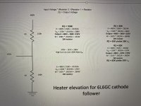
All the parts have come in for the refurbishment of my Compactra, including a 6.3 VAC transformer for the 6L6GC cathode follower. The tube has 378 VDC on the cathode - way over the max heater to cathode voltage. Some say just leave the Vhk voltage alone as it has worked fine (as far as I know) for decades. The elevation voltage level would have to be quite high just to get the Vhk barely in spec. 90 VDC is about the highest elevation voltage I have ever heard of. Would almost 200 VDC be too high? My voltage divider math is attached. Thanks
Attachments
Just a quick update. Progress is slow but moving forward. Several decades of dirt and corrosion removed. First pic shows new three wire power cord, inrush limiter (look close), new caps, new tube sockets, heater wiring and output jacks w/ 360 ohm protection resistor. Pic two is top view of chassis. Beefed up power transformer base w/ angle pieces due to its weight deforming the chassis. Added smaller transformer for the 6L6GC cathode follower heater voltage. This thing is heavy and w/ a 15" speaker it makes for a back breaking combo. May have to convert to a head unit. Front panel refurb next.


Looking good, but I would have been tempted to fit those octal sockets so they were under the chassis. Did they not fit? Also, from an aesthetic point of view, the noval sockets could have had the nuts under the chassis, like the octals? Or was there a space issue?
I've to say I prefer the sockets on the chassis, not under. I had the choice when I built my amp and for some reason sockets on top looked better to me.
A keen eye you have there, OldHector. It gets tight inside the chassis which is why I, like the original builder, set the octals on top of the chassis. Eventually I will have to bend over the octal soldering tabs for all to fit nicely. On the nine pin sockets some of the solder tabs came awful close to the socket mounting lock nuts, so I switched them up. The original builder used pop rivets to secure the sockets, and there seemed to be a lot more clearance. On the power tubes I kept the lock nuts on the underside of the chassis for better tube base clearance. Thanks for double checking the layout. It's good to get other people's opinions that may result in a better way to do things.
Seems that it's regulated in name only, somewhat like our financial industry.
Puts the screen at a fixed percentage of B+; a good way to stabilize operating point as B+ sags. Bogen did that a lot - cheaper than oversizing the power transformer.
As for H-K voltage... put a large resistor from heater to cathode - H-K voltage will be zero.
- Home
- Amplifiers
- Tubes / Valves
- 6L6 Voltage Regulator