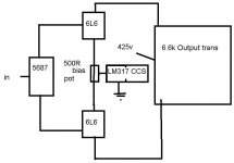
If you mean "will it sink 125mA of DC?" Yes, it will. If you mean "will it be a true constant current sink with high output impedance above 100Hz?" Then, no. The 317 is quite a reasonable regulator, but it doesn't belong that close to audio.
You will get far better results using a real audio transistor such as a BD131. Connect its collector to the wiper of your pot. Take the emitter to ground via a 16 Ohm resistor. Apply 2.65V to the base, and you will have a 125mA current sink. Make that 2.65V slightly variable, and the anode current will be adjustable.
Edit: I thought you wanted to keep this thing simple? What's wrong with resistor/capacitor bias at the output stage?
I am also in support of the resistor cathode bias or fixed bias. Once you have an amp up and running you can always experiment with adventurous biasing schemes. It will be very surprising if you actually prefer the sound with a 317.
I would heartily agree with analog and EC. Why complicate a simple task?
And I would add that if what you're after is punchy bass (as you said in your other post), class-A zero feedback is probably not the way to go. That will tend toward looser, softer bass, with less power available.
And I would add that if what you're after is punchy bass (as you said in your other post), class-A zero feedback is probably not the way to go. That will tend toward looser, softer bass, with less power available.
oh yes... my wrong..
i was told that a current sink using the 317 sounded quite good. it supposedly tightened up the bass.
the way it looks, i may have to look into a NFB or revert back to a proven design.
i was told that a current sink using the 317 sounded quite good. it supposedly tightened up the bass.
the way it looks, i may have to look into a NFB or revert back to a proven design.
punchy bass
That completely slipped my mind. The zero nfb approach is probably best for simpler acousic music and unless you really make an effort may disappoint with rock. Have you looked at some of the Audio Research amps? They have a mod for a 6L6 Dynaco which very possibly has great bass.
Deep and punchy bass is possible even with zero nfb and even in SE designs but is certainly not guaranteed. It will greatly depend on your speakers ability to play without too much control from the amp and on serious attention towards the PS.
dire straits and eddie van halen
Analog, that should be a clue that hacknet is not using speakers with a Bessel alignment. 😉
i`m running a pair of open baffles with a sub crossing at 90hz. i would not consider my system to be bass friendly. i saw the schematics for a Dynaco which is based on the williamson.
would that be a better bet?
would that be a better bet?
I don't think the Dynaco is better than Williamson. I've had both (still have an ST70 somewhere) but a comparison would be unfair - my Willaimson used all Partridge iron and PIO caps while the Dynaco is completely stock. Williamson is triode wired class A and the Dynaco is AB ultralinear with a very marginal PS.
What i had in mind was an AR modded Dynaco. It looks pretty much like a D76 and while AR is not hip with the diyers it produces exemplary bass and solidity and is really able to rock.
Why don't you try listening to a vintage AR amp and see what you think?
What i had in mind was an AR modded Dynaco. It looks pretty much like a D76 and while AR is not hip with the diyers it produces exemplary bass and solidity and is really able to rock.
Why don't you try listening to a vintage AR amp and see what you think?
i`ve not heard but i`ll look forward to listening to one.
i was looking at this schematics and was quite acrosound 6l6
what do you think. i think its simple enough for a beginner to start with....
i was looking at this schematics and was quite acrosound 6l6
what do you think. i think its simple enough for a beginner to start with....
this schematics
Not bad. It will certainly get you started and if you build it as a prototype will certainly let you experiment with a lot of different configurations
i`ve got a question thou.
i see a X marked at the cathode and there is another "to X" at to what sees like a heater hum pot. is this to bring the heater`s potential closer to the cathode? do i just have to connect "to x" to x?
i see a X marked at the cathode and there is another "to X" at to what sees like a heater hum pot. is this to bring the heater`s potential closer to the cathode? do i just have to connect "to x" to x?
another question, i see that the screen is tied to a 270v line. i`m a noob, please answer my silly question.
is this tube operating in tetrode or triode? i guess tetrode rite?
is this tube operating in tetrode or triode? i guess tetrode rite?
The zero nfb approach is probably best for simpler acousic music and unless you really make an effort may disappoint with rock. Deep and punchy bass is possible even with zero nfb and even in SE designs but is certainly not guaranteed. >
Yes indeed - I can get deep bass but I wouldn't call it tight. This is the real area of sacrifice. There again, I listen to small scale classsical and jazz music so zero NFB is really in its element - the double bass sounds a bit boomy but not overly so - I can live with it. There again, I'm a double bass player. The cobbler's children have no shoes! Andy
Yes indeed - I can get deep bass but I wouldn't call it tight. This is the real area of sacrifice. There again, I listen to small scale classsical and jazz music so zero NFB is really in its element - the double bass sounds a bit boomy but not overly so - I can live with it. There again, I'm a double bass player. The cobbler's children have no shoes! Andy
hacknet said:
is this tube operating in tetrode or triode? i guess tetrode rite?
Rite.
hacknet said:i`ve got a question thou.
i see a X marked at the cathode and there is another "to X" at to what sees like a heater hum pot. is this to bring the heater`s potential closer to the cathode? do i just have to connect "to x" to x?
Also rite. 😉
This connection puts the heaters above the cathodes in potential, which can (with some tubes) reduce hum compared to grounding it.
Oh, yeah, and don't take the schematic literally and use a selenium stack for the screen supply. Use a proper silicon HV rectifier (high speed one, if you prefer). When you start getting the itch to experiment, regulating this supply will be the single most effective change you could make.
selenium stack? i did a seach and i still don`t get it. mind explaining?
you advise regulating? i always thought power amps were always better left hanging as current was always a problem with regulating.
you advise regulating? i always thought power amps were always better left hanging as current was always a problem with regulating.
Hi,
The two diodes in series on the Acrosound 6L6 schematic you linked to.
The screengrid of the 6L6.
Leave it hanging for the time being....😉
selenium stack?
The two diodes in series on the Acrosound 6L6 schematic you linked to.
you advise regulating?
The screengrid of the 6L6.
Leave it hanging for the time being....😉
To amplify Frank's comments, the schematic shows a stack of selenium rectifiers running the screen supply. That's an old technology which, happily, has not become retro-cool (though maybe this year someone will "discover" that selenium rectifiers are enormously better-sounding because they perform so badly).
And as he says, build as-is for the first go-round, but do plan in enough chassis space to add regulation to that screen as your first upgrade.
And as he says, build as-is for the first go-round, but do plan in enough chassis space to add regulation to that screen as your first upgrade.
- Status
- Not open for further replies.
- Home
- Amplifiers
- Tubes / Valves
- 6L6 Design Phase