Hi, I have a bassman clone I'm building and my tubes, russian 6L6's are glowing red at 420 volts and 47mA of current. When I add more negative bias voltage to get the red out, the plate voltage goes up to about 470v with only 22mA. Clearly within the plate dissipation limits.
I did notice since I move to Minnesota this week that the wall voltage is at 119v versus 115 in my California home.
I can't figure out what's going on...
I did notice since I move to Minnesota this week that the wall voltage is at 119v versus 115 in my California home.
I can't figure out what's going on...
Are they really 6L6GC? or 5881/6L6? The latter can only take 400 volts.
Are you measuring the current properly? Red-plate seems like far more current than 40 mA.
What is the voltage on the screens?
I see you are hooking the screens up to "B".
Seriously try disconnecting that and hooking them up to
a more sensible voltage, like "D" or "E". (i.e., less than 350 volts on screen, as per design-center values in typical operation).
At least see if the tubes work like that first.
If they can't work in any scenario, I hate to say it,
but maybe the tubes are already bad/cooked,
or maybe you've cooked the screens letting them go into runaway.
First measure the voltages all along your Power Supply,
then pick a low one for screens, and isolate that with another resistor in series/cap to ground to keep the current from influencing the other stages.
That is, figure out a good resistor value and hook it up to "B", with a cap to ground, dropping the screen voltage by 200 volts (use a 10 watt or higher resistor).
One other possible thing you MUST check.
Disconnect your feedback loop from the output tranny,
because you may have wired it backwards, i.e., POSITIVE FEEDBACK by mistake!!!!
hardwire a 100 ohm resistor across the output tranny (where the speakers would go),
to protect the transformer from spikes. It won't affect sound.
Don't put an input signal into the amp while the feedback loop is disconnected.
Last edited:
When you reduce the current through the tubes you are dropping less voltage across your power supply and the output voltage goes up. It may be best if you put some series resistance between your first cap and the rectifier.
Check for an ultrasonic oscillation. Connect your DVM across the speaker terminals and set to AC volts. With no signal the DVM should measure in the 10s of millivolts or less. An oscillation will read several volts.
From what I know-limited-the screen voltage should be close to, but lower than the plate voltage. But with the max according to the 6L6 data sheets, 450 volts on the screen, would that extra 7 to ten volts higher be a problem?
I'm sure they are 6L6GC, that's the spec I bought them, but they are with Russian print. And I don't think less than 350 volts on the screens sounds right to me.
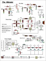
I can add a small resistor between the first cap and rectifier, like I have on the low power side of the switch shown which is 1.5K. And, I will try testing the current in the low power mode too, to see if it's stable at around 19 to 20 watts dissipation. Any size recommendation for that resistor Printer2?
I'll also check for the ultrasonic oscillation.
As for the feedback loop, I have it wired correctly. It is a variable feedback control to go from a mere 1% to 22%. It sounds okay, just the current is low and I cannot get close to the max dissipation of 21 watts, which I like a target of about 18-19 watts dissipation.
Thanks for the suggestions...
I'm sure they are 6L6GC, that's the spec I bought them, but they are with Russian print. And I don't think less than 350 volts on the screens sounds right to me.
I can add a small resistor between the first cap and rectifier, like I have on the low power side of the switch shown which is 1.5K. And, I will try testing the current in the low power mode too, to see if it's stable at around 19 to 20 watts dissipation. Any size recommendation for that resistor Printer2?
I'll also check for the ultrasonic oscillation.
As for the feedback loop, I have it wired correctly. It is a variable feedback control to go from a mere 1% to 22%. It sounds okay, just the current is low and I cannot get close to the max dissipation of 21 watts, which I like a target of about 18-19 watts dissipation.
Thanks for the suggestions...
Please note: Audiophile builders, go away. These things are build different then those boutique amps.
no, the little bit of voltage increase would add some headroom
I run mine 520V plate, tie a 1 k resistor from screen to plate.
I would tie the screen resistor to the B+ connection going to the center tap of the output transformer then use a switch to different taps on your power supply to the output transformer/screen supply.
On the output tubes, the cathode resistor should be low in value (if not directly tied to ground). 1 ohm, 10 ohm, and 100 ohm (with bypass cap around 220uf ) works nice, but I like a piece of wire thank you.
on bias, I would make that as a master volume control that is set up so I can go from cut off to OD (in a voltage divider network).
the more ways it can go non-linear the better.
Dave, not sure I fully understand. the 1K resistor between the screen and plate is fine, but do you mean connecting the that resistor to the B+? And which end the plate or screen? I am assuming the plate side, but want to be sure of what you are saying. And then the switch to different taps on my power supply also confuses me.
Also, the cathode resistor shown in the bias circuit is for switchable cathode-fixed bias.
I have the values set so I can do the cutoff to OD on the bias pot, but I'm having trouble finding the exact value that does not go too far into OD and make the plates glow.
I had a pair of Baldwin 6L6's but damaged them by when I accidentally touched the bias line to the B+: BIG SPARK AND LOUD POP.
Not sure if the new russian tubes are that different of if I damaged something else.
Thanks...
Now I am wondering if these tubes are rated as high as the 6L6GC. They have 6n3c and the number 0184 etched on the glass. I've tried to look up specs for this but don't get consistent info.
I did test the current in the low power mode with 365 volts on the plates. The current was 53mA, which calculates to ~19 watts dissipation. That is what I expect and want.
Does anyone have any info about these tubes that may explain why I cannot get the power dissipation I am targeting?
The bias voltage, when adjusted to get rid of the red glow is what I expect, about -45 volts. But the current running through them is quite low.
Also in cathode bias mode, the current is only 12mA. According to the Weber bias calculator online, they should be running at about 29mA given the parameters I have:
Plate voltage-489v
Cathode voltage-46v
Cathode resistor value-750 ohms
Now I am wondering if these tubes are rated as high as the 6L6GC. They have 6n3c and the number 0184 etched on the glass. I've tried to look up specs for this but don't get consistent info.
I did test the current in the low power mode with 365 volts on the plates. The current was 53mA, which calculates to ~19 watts dissipation. That is what I expect and want.
Does anyone have any info about these tubes that may explain why I cannot get the power dissipation I am targeting?
Any 6L6 will run good at 350-400 v.
If they won't run properly at higher voltages,
they probably aren't made to...why damage them?
The bias voltage, when adjusted to get rid of the red glow is what I expect, about -45 volts. But the current running through them is quite low.
Also in cathode bias mode, the current is only 12mA. According to the Weber bias calculator online, they should be running at about 29mA given the parameters I have:
Plate voltage-489v
Cathode voltage-46v
Cathode resistor value-750 ohms
46v / 750 r = .061 = 30 mA per tube.
If you're reading 46v, then you must be conducting 60 mA!
How are you trying to measure current?
These values look good:
I'm running my Svetlana 6L6GC at:
Plate = 520 v
Bias = - 50 v
Rk = 1500 R (1K5) per tube.
Idle current = 33 mA per tube (aiming for 40 mA idle).
The cathode resistor is shared so, your numbers would be in half, yes... And that's assuming my resistor is actually 750 ohms. So that formula would then read: 46/1500=.0305 @ ~15mA per tube.
That is strange, the first resistor I used was 250 ohms and got over 100mA. It took awhile to get to the 750 value and figure out that was good. But that was with other tubes that I mentioned. These tubes must be what is causing this change...
But I did not know that formula for figuring it out, thanks.
To test current, the probes are on the B+ and the plate pin.
I will have to assume that the tubes are not a GC equivalent, so they'll be used for the next few projects.
Before I try it, can I test screen current in the same way: B+ to screen pin? I've blown too many fuses in my meter to want to even test it... I'd rather someone just say yes or no.
Thanks
Thanks
Before I try it, can I test screen current in the same way: B+ to screen pin? I've blown too many fuses in my meter to want to even test it... I'd rather someone just say yes or no.
Thanks
A meter on the right setting should take 750 volts (max for most meters).
But you cannot measure with a signal on tube,
since the swing could be 100 or more volts +- the supposed value.
One way to measure screen voltage (and current) is to
measure between the B+ and the screen pin.
There would / could be a voltage drop across the screen resistor (if there is one).
This will be much smaller than the total B+ powersupply.
Lets say the difference was 20 volts.
If you know the B+ (HT) is 500 volts, then the screen is 480 (or 520! check polarity).
This is safe for the meter but NOT FOR YOU: (!!!)
Remember that there is still 500 volts to ground on your meter clip/ prod, or lead.
You should be on a rubber mat,
wearing rubber soled running shoes,
and ALWAY HAVE ONE HAND IN POCKET
AWAY FROM ANY GROUND:
Its NOT safe for your left hand for instance to be touching a chassis, or leaning on a grounded bench or power supply, etc.
The multimeter leads should be shielded,
and you should be careful not to slip or short them to anything else like the chassis.
Also, when you look up to read meter,
and your eyes are away from the meter lead,
stay perfectly rigid and don't move.
Then look back to the circuit quickly.
Try to use leads that are mostly insulated, with no bare metal hanging out. Clip your leads on firmly if possible,
and don't just poke around with your meter lead:
that's how accidents happen.
Anytime you clip your meter to HV to take a reading,
hurry it up, then shut power off and remove the clip.
NEVER leave the clip of a meter on a HV connection,
because the whole meter (including the other lead) will be 'hot'!!!
Even after you shut off the amp.
Last edited:
Yes, for voltage I don't have the fuse problem, it was for testing current that I would blow fuses.
Thanks for the safety tips too.
So, do I test the screen current the same way as plate current?
Thanks for the safety tips too.
So, do I test the screen current the same way as plate current?
Yes, for voltage I don't have the fuse problem, it was for testing current that I would blow fuses.
Thanks for the safety tips too.
So, do I test the screen current the same way as plate current?
To be clear, the only way you can test the B+ is to connect between it and ground.
You should do this on three locations:
(1) the powersupply positive cap (be careful!)
(2) the output transformer center tap.
(3) the Plate pin on the tube(s).
They should all be about the same voltage (to ground).
The screen voltage can be measured at the pin
when there is no signal on the amp,
either :
(1) from ground (in your case less than 750 volts).
(2) from the B+ (then subtract the difference).
Never forget the one hand in pocket rule until you have it as a fixed habit.
Nazaroo: CURRENT!!
Not voltage. I know how to measure voltage. I was asking about current. Milliamps not volts.
To test the plate CURRENT I touch the B+ with one probe and the plate pin with the other.
Do I do the same with the screen CURRENT?
Not voltage. I know how to measure voltage. I was asking about current. Milliamps not volts.
To test the plate CURRENT I touch the B+ with one probe and the plate pin with the other.
Do I do the same with the screen CURRENT?
I think I understand now.
For your information, most people don't ever attempt to measure current in High Voltage circuits directly.
You should instead measure the voltage-drop across a known resistor,
and calculate the current from Ohm's Law.
Furthermore, you should always do this from the LOW VOLTAGE end
of the circuit, namely a resistor connected to ground,
or near ground, such as in the cathode of a tube circuit,
NEVER at the HIGH Voltage end, where death is immanent.
One of the main reasons for this is that the incredibly cheap and crappy insulation material on the leads of your multimeter
WILL NOT PROTECT YOU FROM HIGH VOLTAGE.
This 'insulating' material will instead conduct electricity and kill you.
So E.Engineers do this for safety reasons among other things.
I think I know what you are trying to do now,
and I should warn you immediately,
that most multi-meters are not designed to measure current in High Voltage circuits at all,
and to try to do it is foolish and an expensive way to wreck meters and burn money, as well as risk death.
Let me explain: We only say that '30 volts RMS (Root Mean Square) is equivalent to 30 volts D.C., because over relatively long time periods (far greater than the cycle-period) it will produce the same heat on average in a given fixed resistance as 30 volts DC would.
That is where the similarity STOPS.
Other than this convenient ad hoc heat calculation, there is nothing whatever similar between AC currents/voltages and DC currents/voltages.
Although your multimeter can measure AC current, it makes this same 'heat-equivalence' calculation, but for the purposes of tracking screen currents its just about useless, and also downright dangerous!
Here is why:
(1) If you are measuring the screen current during 'idle' (no musical signal), then this can be done by simply measuring the voltage-drop across the screen resistor.
But what is it you think you are measuring?
Its not A.C. current! Unless in idle conditions the tube is actually conducting electrons from the screen to the plate, there can be no true A.C. current. Instead, the only possibility is a pulsed D.C. current, but the most likely occurance will be a steady D.C. current from the cathode through the screen to the B+ either directly or through the Output transformer. The only A.C. will be a faint powersupply ripple from the B+ and the heater element.
(2) If you want to measure the screen current during the amplification of a musical signal, you are risking death!
Why? Because suppose you pump in a healthy sine-wave and it is amplified to 30 watts RMS. This huge voltage swing (say 250 volts) is dancing on the plate and screen, and it will ride on top of the already High Voltage B+ (say 500 volts).
Now not only will the voltage easily exceed the 750 volt maximum your meter can handle, but it will also blow through the 600 volt insulation on 99% of the wire used in amplifiers and in house-wiring.
(3) The multimeter will also lie to you about the voltage, and the risk: It takes samples and displays an AVERAGE signal. Thus it could read "300 volts RMS" on your meter, while in fact, for short periods the actual voltage on your leads could be 1 Kilovolts, enough to easily kill you. The most important thing you must understand with High Voltage and A.C. currents is that your multimeter cannot and will not ever tell you the peak voltages or warn you of the danger lurking in your circuits.
For your information, most people don't ever attempt to measure current in High Voltage circuits directly.
You should instead measure the voltage-drop across a known resistor,
and calculate the current from Ohm's Law.
Furthermore, you should always do this from the LOW VOLTAGE end
of the circuit, namely a resistor connected to ground,
or near ground, such as in the cathode of a tube circuit,
NEVER at the HIGH Voltage end, where death is immanent.
One of the main reasons for this is that the incredibly cheap and crappy insulation material on the leads of your multimeter
WILL NOT PROTECT YOU FROM HIGH VOLTAGE.
This 'insulating' material will instead conduct electricity and kill you.
So E.Engineers do this for safety reasons among other things.
I think I know what you are trying to do now,
and I should warn you immediately,
that most multi-meters are not designed to measure current in High Voltage circuits at all,
and to try to do it is foolish and an expensive way to wreck meters and burn money, as well as risk death.
(1) You shouldn't be trying to measure current with a multimeter by connecting it between B+ and plate.
This is an accident just waiting to happen.
(2) The nature of AC current is that it is much more slippery and esoteric than D.C. current.
It is always in the form of AVERAGE current, and this is a mathematical average, an APPROXIMATION, based on the idea of 'work done' or 'heat generated'.
Let me explain: We only say that '30 volts RMS (Root Mean Square) is equivalent to 30 volts D.C., because over relatively long time periods (far greater than the cycle-period) it will produce the same heat on average in a given fixed resistance as 30 volts DC would.
That is where the similarity STOPS.
Other than this convenient ad hoc heat calculation, there is nothing whatever similar between AC currents/voltages and DC currents/voltages.
Although your multimeter can measure AC current, it makes this same 'heat-equivalence' calculation, but for the purposes of tracking screen currents its just about useless, and also downright dangerous!
Here is why:
(1) If you are measuring the screen current during 'idle' (no musical signal), then this can be done by simply measuring the voltage-drop across the screen resistor.
But what is it you think you are measuring?
Its not A.C. current! Unless in idle conditions the tube is actually conducting electrons from the screen to the plate, there can be no true A.C. current. Instead, the only possibility is a pulsed D.C. current, but the most likely occurance will be a steady D.C. current from the cathode through the screen to the B+ either directly or through the Output transformer. The only A.C. will be a faint powersupply ripple from the B+ and the heater element.
(2) If you want to measure the screen current during the amplification of a musical signal, you are risking death!
Why? Because suppose you pump in a healthy sine-wave and it is amplified to 30 watts RMS. This huge voltage swing (say 250 volts) is dancing on the plate and screen, and it will ride on top of the already High Voltage B+ (say 500 volts).
Now not only will the voltage easily exceed the 750 volt maximum your meter can handle, but it will also blow through the 600 volt insulation on 99% of the wire used in amplifiers and in house-wiring.
(3) The multimeter will also lie to you about the voltage, and the risk: It takes samples and displays an AVERAGE signal. Thus it could read "300 volts RMS" on your meter, while in fact, for short periods the actual voltage on your leads could be 1 Kilovolts, enough to easily kill you. The most important thing you must understand with High Voltage and A.C. currents is that your multimeter cannot and will not ever tell you the peak voltages or warn you of the danger lurking in your circuits.
Last edited:
To test the plate CURRENT I touch the B+ with one probe and the plate pin with the other.
NO NO NO!
You should NEVER measure the current this way!
This is the most foolish thing you can do, especially
if there is a potential music signal or test signal in the amp.
Measure the Plate current during idle by measuring the voltage across the cathode resistor or load,
and calculate the current using Ohm's Law.
Never use the "current" function on your multimeter for High Voltage.
No NO NO NO NEVER!Do I do the same with the screen CURRENT?
If you are trying to measure screen current during idle,
measure the voltage across the screen resistor and calculate the current.
NEVER MEASURE IT DIRECTLY.
If you are trying to measure screen current during full amplification of a signal,
You have to CALCULATE it by subtracting the Plate current
from the Cathode current!
- Status
- Not open for further replies.
- Home
- Live Sound
- Instruments and Amps
- 6L6 current-voltage problem