Could be how the RCA grounds or volume control grounds are connected
to the power supply common. Maybe the filament rectifier circuit is adding
noise to the grounding. Try feeding the filaments DC from an external 12V
power supply, disconnecting the pcb filament supply by removing D1,
and see if the hum is reduced.
to the power supply common. Maybe the filament rectifier circuit is adding
noise to the grounding. Try feeding the filaments DC from an external 12V
power supply, disconnecting the pcb filament supply by removing D1,
and see if the hum is reduced.
Last edited:
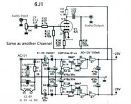
It's only a half wave rectifier in the filament supply, so lots of ripple will be there.
If this helps, maybe you can rework it as a full wave rectifier with more capacitance.
If this helps, maybe you can rework it as a full wave rectifier with more capacitance.
Thanks. I searched the forum for '6J1' repeatedly and it always ended with 'sorry no results'...not sure why.
I have some success with hum. I separated normal power supply, now 14 volts AC, from heater, now 12 volts DC. I use separate trafo. Hum went down from 3-4 mV to about 0.3 mV.
Since i separated these two supplies, i can raise the voltage, but i need to replace power supply caps, since they are rated to 35 volts.
Last edited:
Great, thanks Ketje, will test all.
I thought that R16 was only drawn incorrectly in the schematics, but in reality was ok. Will check that out.
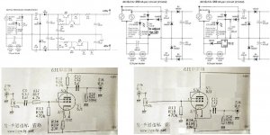
Most important suggestion in your picture is the change from preamp to buffer. That of course will require some copper trace cutting. I will consider doing so.
Well, i am already using two separate trafos, so i got that already on my own. 🙂
I thought that R16 was only drawn incorrectly in the schematics, but in reality was ok. Will check that out.
Most important suggestion in your picture is the change from preamp to buffer. That of course will require some copper trace cutting. I will consider doing so.
Well, i am already using two separate trafos, so i got that already on my own. 🙂
I replaced some caps in the power amp and i am running it +/- 48 volts, which is significantly better than original.
If it's only in the schematic, no problem then.Great, thanks Ketje, will test all.
I thought that R16 was only drawn incorrectly in the schematics, but in reality was ok. Will check that out.
The two times 12V is not two trafos, simply a 24V with center tap.Well, i am already using two separate trafos, so i got that already on my own.
Mona
Ketje, I understand perfectly what your picture shows...
I was describing what I did, not that any one cares. I use two separate adapters to power it. One 12 DC adapter just to power the heaters. One separate AC adapter to power the voltage multiplier. This way I can swap the AC adapter with increasing voltage, I use 18 volts AC now, giving me +/- 48volts volts for tubes. Sounds better this way, then measly +/- 28 volts.
I will be beefing up some filtration here and there, but otherwise I am almost done with it. No need to waste time on cheap project.
Or you could use one of these and have dial-a-volt 🙂
DC-DC 8-32V to +-45V-390V Step-up ZVS High Voltage Capacitor Module Charge Board | eBay
DC-DC 8-32V to +-45V-390V Step-up ZVS High Voltage Capacitor Module Charge Board | eBay
Thanks for the suggestion kodabmx. Minor issue is that i have already replaced original caps rated 35 volts to new ones for 50 volts. Therefore i do not want to exceed 100 volts total right now.
Thanks anyway.
Thanks anyway.

You'r not the first with problems with this circuit.
R16 to ground not -Vb !
Some sugestions to improve.
Mona
Hi Ketje,
I modofied this preamp to buffer. And its indeed very clean sounding and transpareny with almost unity gain..May you please explain whether this is functioning similar to 'The Harmonic Restorer' described in tubecad.com?
- Status
- Not open for further replies.
- Home
- Amplifiers
- Tubes / Valves
- 6J1 preamp