Hi,
I'd like to start of by saying the lockdown was driving me insane, so I decided to start my old hobby of breaking and making small electronic circuits. I've not done this for a while.
I love buying cheap stuff hoping it works, I purchased a Fosi Audio T20 Tube Amp and was impressed with it. See profile website for video review.
So I decided to buy a cheap Chinese "Tube Amp", take it apart, draw a schematic, design a new PCB and make it again, hopefully slightly better.
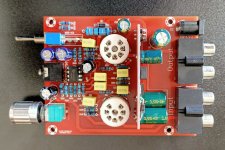
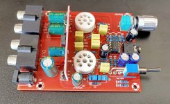
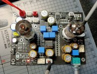
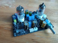
The amp is from AliExpress, and it was £18. It came assembled and was supplied with 6J1 tubes. The headphone amplification is done via NE5532P, the tubes are supplied with 100vdc via a DC-DC booster and the input supply is 12vdc.
DIY 6J1 2 Tube Headphone Amplifier Kit Preamp Tube Board Preamplifier Post amplifier with 3.5MM Headphone / Preamp Output 12V DC|Headphone Amplifier| - AliExpress
To me it sounded fine, I did not notice any overheating\distortion\hum at normal volume levels (did not go all the way up, I value my hearing). it also worked with other EF95 tubes like M8100.
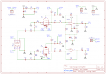
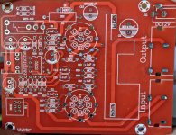
So I desoldered it and drew up a schematic, please note it is the first pass of my board analysis so there maybe a mistake or two.
I love the simplicity of the design, however the pcb tracks were very poorly done, there were vias on the postive rail when it was completely unnecessary, the ground tracks were in a star format, and the soldering was poor.
As I don't know much about tube amps and op amps, I started reading and watching Youtube videos and noted the following based on my limited knowledge and understanding:
Please don't say this is not a tube amp, go and make a proper tube amp with 400vdc and no semiconductors 🙂
Pictures and schematic below.
BTW I searched the forum and could not find anything on this board, sorry if something similar has been posted already.
Thanks
I'd like to start of by saying the lockdown was driving me insane, so I decided to start my old hobby of breaking and making small electronic circuits. I've not done this for a while.
I love buying cheap stuff hoping it works, I purchased a Fosi Audio T20 Tube Amp and was impressed with it. See profile website for video review.
So I decided to buy a cheap Chinese "Tube Amp", take it apart, draw a schematic, design a new PCB and make it again, hopefully slightly better.
The amp is from AliExpress, and it was £18. It came assembled and was supplied with 6J1 tubes. The headphone amplification is done via NE5532P, the tubes are supplied with 100vdc via a DC-DC booster and the input supply is 12vdc.
DIY 6J1 2 Tube Headphone Amplifier Kit Preamp Tube Board Preamplifier Post amplifier with 3.5MM Headphone / Preamp Output 12V DC|Headphone Amplifier| - AliExpress
To me it sounded fine, I did not notice any overheating\distortion\hum at normal volume levels (did not go all the way up, I value my hearing). it also worked with other EF95 tubes like M8100.
So I desoldered it and drew up a schematic, please note it is the first pass of my board analysis so there maybe a mistake or two.
I love the simplicity of the design, however the pcb tracks were very poorly done, there were vias on the postive rail when it was completely unnecessary, the ground tracks were in a star format, and the soldering was poor.
As I don't know much about tube amps and op amps, I started reading and watching Youtube videos and noted the following based on my limited knowledge and understanding:
- First thing I noticed was that OpAmps are designed for Positive and Negative supplies, but can be made to work with a normal DC supply by offsetting voltages (excuse my terminology).
- I also noted some of the coupling caps seem too high, input ones are 1uf and the output is at 220uf.
- The tube cathode resistor R14 and R19 seem to be missing a capacitor, I know this is optional but won't know what will happen unless I try the circuit with the capacitors in place.
- I don't understand the point of R1 and D1, the power supply is 12v and the two tube heaters in series should be fine with 12v.
- I tried to work out if the tubes were biased properly (R15, R14 - R20, R19), but the maths confused me in the end.
- The potentiometer value seems low, most amps schematics I've seen seem to commonly use 100K.
- If the DC-DC booster is supplying 100v, surely R15 and R20 is causing a voltage drop meaning the plate is getting less than the recommended voltage as per tube specs that I've looked up.
Please don't say this is not a tube amp, go and make a proper tube amp with 400vdc and no semiconductors 🙂
Pictures and schematic below.
BTW I searched the forum and could not find anything on this board, sorry if something similar has been posted already.
Thanks
Attachments
Last edited:
Do you have a link to where you bought it?
First improvements would be to get a genuine opamp, that one is 99% certain fake, or 1% a counterfeit copy which may or may not come close to the original. And replacing C2, C4, C10, C14 and C15 with a slightly better cap might also help a bit.
First improvements would be to get a genuine opamp, that one is 99% certain fake, or 1% a counterfeit copy which may or may not come close to the original. And replacing C2, C4, C10, C14 and C15 with a slightly better cap might also help a bit.
I've updated the OP with the link, other sellers sell them too, although it's not a common board.
I already have a selection of genuine op amps, I plan on replacing all the components.
Kemet\Epcos for PET caps, and Nichicon audio caps for the electrolytics. I tested most of the components that came with this board, they all seem to be within tolerance.
I plan on sharing the gerber and making a video of me putting it all back together.
I also plan on experimenting with this board:
NCH6100HV High Voltage DC Step Up Converter Power Supply Module For Nixie Tube Glow Tube Magic Eye Board DC 12V 24V to 85 235V|high voltage|dc step upstep up - AliExpress
It's for Nixie tubes, but I think it can deliver enough current for EF95 tubes.
It seems a good choice as learning exercise: a textbook schematic of a triode tube voltage gain stage, followed by a inverting op-amp amplifier. PCB is clearly labeled. Component values have been tweaked to reduce gain and get some distortion, so it's more of a creative effect device rather than Hi-Fi, but I don't see glaring flaws such as the hum/hisses/clipping that plague many inexpensive low voltage hybrid kits. The schematic seems funny because it is not drawn according to the standards and the tube symbol has the cathode connection in the wrong place, but it seems to me mostly ok. To learn more about the schematic and get an answer for most of the questions in the first post, I suggest the valvewizard.co.uk web site for the triode section, and the venerable National Semiconductor application note AN116 for the op amp stage. You will therefore learn that the circuit can be improved in several ways, wich are more effective than simply exchanging components for higher quality parts. I haven't cheched the circuit througly, but I do not see bypass capacitor next to the op amp power supply pin, the resistor R12-R17 has an excessive value and is better positioned between socket pin 1 and the grid leaks R13-R18, the pre out output impedence is too high and this output could be better connected in parallel with the headphone output, and so forth. About your question relating to R1 and D1, this is my guess. According to your photos, the cheap switched mode high voltage boost power supply board does not have any input filter; this means that there are negative spikes at ultrasonic frequency superimposed on its input. C13-R1-D1 are there to block/attenuate this noise and reduce the effects on the operational amplifier.
The choice of the tube is also somewhat questionable for me. 6J1 is the cheapest tube good enough to reach the "slight tube distortion at the output" goal. But if a little more quality is required, within the limits of a 90/100V power supply, which will be the best tube that is available at low cost? I can think of 6N9S/6SL7 and 6DJ7/ECC88/6N23, but perhaps there are other better choices.
The choice of the tube is also somewhat questionable for me. 6J1 is the cheapest tube good enough to reach the "slight tube distortion at the output" goal. But if a little more quality is required, within the limits of a 90/100V power supply, which will be the best tube that is available at low cost? I can think of 6N9S/6SL7 and 6DJ7/ECC88/6N23, but perhaps there are other better choices.
Last edited:
Thank you for the feedback, I shall investigate.
I drew the diagram myself using EasyEDA, the valve schematic parts are from user libraries, I did noticed they were topsy turvy, the PCB layout was the wrong way round as well.
My understanding is that a lot of these Chinese tube amp sellers suggest 6J1 can be replace with any 6AK5\EF95, not sure if that should be done or not, plenty of examples on Amazon suggesting that. I also have two 1966 Russian 6J1s that I test with.
I'm running another pass of the circuit board using a wet chalk pen to keep track of the tracks, I'll know soon if there are any mistakes in the schematic.
100v Booster
Hello again,
I haven't forgotten about this, just been busy with work.
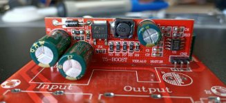
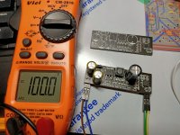
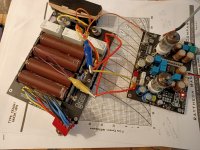
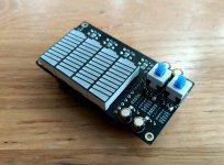
I managed to reverse enigineer the 100v DC booster and made my own version.
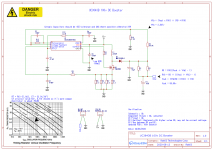
The booster is based on the UC3843B chip, I could not find any decent circuit diagrams for this, however I came across this:
Nixie Stuff | Threeneuron's Pile o'Poo
If you scroll down to "TI (Unitrode) UC3843 Based HV Supply" the circuit I reversed engineered is very similar.
So I did all the calculations and verified that the original circuit is indeed all correct and generates the 100v DC out as expected, so I designed the circuit in EasyEDA and made a very slight adustment to Vfb to produce exactly 100v out.
When I made the circuit and put it to the test I got 360v DC out! dang! I repeated the test and still same, so I examined the components and everything looked good, I then tested it again and got 100v DC out, what gives?
I measured the voltage (Vfb) between R3 and R10 and the correct voltage is shown 2.537.
Has anyone played around with the UC3843B, anyone have any thoughts.
Is it bad that I used a 100v Schottky diode on the 100v out (I have ordered some higher voltage ones)
Note: All components used are non fakes and high quality.
Attached schematic with Vout and Vfb calculations. (
Attached picture to show I really am getting a stable 100v DC out now.
US3843B PDF https://www.onsemi.com/pub/Collateral/UC3842B-D.PDF
Thanks
Hello again,
I haven't forgotten about this, just been busy with work.
I managed to reverse enigineer the 100v DC booster and made my own version.
The booster is based on the UC3843B chip, I could not find any decent circuit diagrams for this, however I came across this:
Nixie Stuff | Threeneuron's Pile o'Poo
If you scroll down to "TI (Unitrode) UC3843 Based HV Supply" the circuit I reversed engineered is very similar.
So I did all the calculations and verified that the original circuit is indeed all correct and generates the 100v DC out as expected, so I designed the circuit in EasyEDA and made a very slight adustment to Vfb to produce exactly 100v out.
When I made the circuit and put it to the test I got 360v DC out! dang! I repeated the test and still same, so I examined the components and everything looked good, I then tested it again and got 100v DC out, what gives?
I measured the voltage (Vfb) between R3 and R10 and the correct voltage is shown 2.537.
Has anyone played around with the UC3843B, anyone have any thoughts.
Is it bad that I used a 100v Schottky diode on the 100v out (I have ordered some higher voltage ones)
Note: All components used are non fakes and high quality.
Attached schematic with Vout and Vfb calculations. (
Attached picture to show I really am getting a stable 100v DC out now.
US3843B PDF https://www.onsemi.com/pub/Collateral/UC3842B-D.PDF
Thanks
Attachments
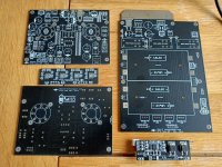
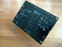
Ok, I've being making slow but steady progress. I've solved the issues I had (I think).
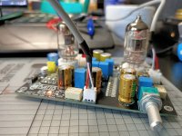
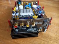
The tube circuit has been modified now after some research and feedback received here, I believe the schematic is now more a standard design. I've recalculated the bias and increased the plate voltage. I've also incorporated the DC HV booster on the main board.
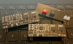
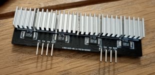
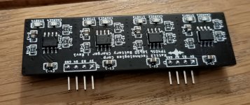
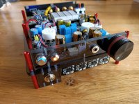
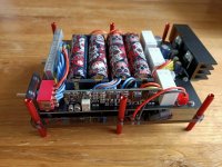
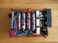
The amp now runs on battery (as well as mains if needed). A seperate board holds 4 18650 batteries, I made a protection circuit as well as charger circuit, it's all modular. The battery board has a buck covertor for supplying the battery charging module, and it has a linear 12v regulator for supplying a clean DC to the amp from the 16.8v batteries.
I'm redesigning the battery protection circuit to include a relay so the protection is not deactivate on startup. The build will also include a BT module and a battery indicator (not pictured).
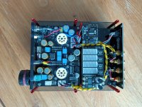
All this will be neatly housed in a perspec case. I expect the overall size to be 140mm(d), 60mm(h) and 122mm(w).
Everything you see here is what I designed and made.
How does it sound? Sounds great when running on batteries, no hum or hiss. I've not properly tested it running on the mains yet. Battery run time is 8 hours.
The tube circuit has been modified now after some research and feedback received here, I believe the schematic is now more a standard design. I've recalculated the bias and increased the plate voltage. I've also incorporated the DC HV booster on the main board.
The amp now runs on battery (as well as mains if needed). A seperate board holds 4 18650 batteries, I made a protection circuit as well as charger circuit, it's all modular. The battery board has a buck covertor for supplying the battery charging module, and it has a linear 12v regulator for supplying a clean DC to the amp from the 16.8v batteries.
I'm redesigning the battery protection circuit to include a relay so the protection is not deactivate on startup. The build will also include a BT module and a battery indicator (not pictured).
All this will be neatly housed in a perspec case. I expect the overall size to be 140mm(d), 60mm(h) and 122mm(w).
Everything you see here is what I designed and made.
How does it sound? Sounds great when running on batteries, no hum or hiss. I've not properly tested it running on the mains yet. Battery run time is 8 hours.
Attachments
Looks very impressive!
Are you looking for a business opportunity? I think there are some modues that would find a market. For instance out-of-bias tube protection, screen regulators, choke replacements.
Are you looking for a business opportunity? I think there are some modues that would find a market. For instance out-of-bias tube protection, screen regulators, choke replacements.
The PCB came for the battery protection circuit, I haven't had the time to make it yet. I redesigned the battery section to supply 4.55v to the TP4056 battery module, this reduced the charging module PCB temp from a finger burning 75degrees to 45degrees.
The battery protection cuts off at 3.2v as per design and the charge cutoff is 4.18v (0.2v below design - bonus), there is no balance as I didn't see a need for it if I use good batteries. The protection kicks in anyway when the cells go out of balance. I've also added extra functions like the ability to turn of the charger when plugged into the mains.
I've been listening to it for many hours, on battery there seems to be zero noise (could be because I'm 41 years old and starting to go deaf). It sounds amazing, I've tested with 2 decent heaphones that are 32ohms and nothing like HD600s, just Sony MDR-1R and Master & Dynamic MW60.
I did notice a faint hum while running on mains on the right channel, you can't hear it when playing music, now this could be due to nearby intererence, I haven't been able to test by moving it away from other electrical cables yet.
I don't seem to get any hum when I touch the exposed metal components, anyone know if I would get a mild shock with 100vdc? I haven't touched it yet accidently, I've touched 300vdc before and it wasn't nice.
I'm not done with the testing yet.
I had to redesign the bluetooth module as I forgot about the common ground loops you get with these modules, so I redesigned the PCB with mini DC-DC isolator, I've not made it yet.
I've also made a battery level indicator, not necessary but I like making things.
I've made the chassis for it, so not long left before it's complete.
All design changes and schematics will be published here.
I've also realised this is an expensive hobby, so I started to sell surplus\bulk buy components on fleabay, I seem to be making a small profit to cover the cost of this project.
Published circuits and info so far, I only publish once I know it works:
EasyEDA: Ratti3 -
EasyEDA
Blog: Ratti3's Electronics Blog
Attachments

Looks very impressive!
Are you looking for a business opportunity? I think there are some modues that would find a market. For instance out-of-bias tube protection, screen regulators, choke replacements.
Hi, What do you mean? All the stuff I made is readily and cheaply available on fleabay, nearly all the schematics are based on manufacturers specsheets and the tube circuit was based on an existing build, albeit it is a standard tube design.
The only things I did different was use the most expensive components I could fine (Nichicon fine gold caps, branded non fake semiconductors and designed nice looking PCs), yes I made improvements and adjustments but the cost is high compared to buying this ready made.
I reckon with the amount of money I spent I could've bought an exspensive tube amp 😀
But then I wouln't have had fun making this.
After this I may dabble with some 12AXs and electocute myself.
Now that I know how to make my own 12v to HV booster, I plan on making my own nixie clock and do some woodworking for the case.
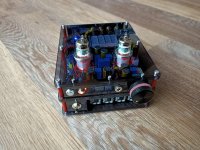
Finished
All finished now, all schematics and BOM available here:
Ratti3 -
EasyEDA
Blog with more info on this project:
Ratti3's Electronics Blog
Video of the project, 3 parts, this is part 1:
How to Make a Battery Operated EF95/6AK5 Tube Amplifier - Part 1 - YouTube
I've made the amp board in such a way, so that it can be used without the additional modules or batteries. All you need is 12VDC and line in and headphones out.
I learnt a lot of things during this, it was challenging and fun, I might return and make a "proper" tube amp another time.
Time for me to move on to something else non audio related.
Attachments
- Home
- Amplifiers
- Tubes / Valves
- 6J1\EF95 Hybrid Tube Preamp, Headphone Amp Teardown and Schematic