If I don't make some mistake reading the graphs, the 6HB6 you have measured here has at least 160mA @ 50V /0Vg (knee), so it make some power. The 6AQ5A has 100mA on knee and make some 8-10W with 8-10k on anode (values from my memory, correct if I made mistakes).The skal tube Pics look like the usual beam type 6HB6.
-------------------------------
RE: DualTriode
Those earlier curves were taken some while back, and I had put a tube on the tracer again to get the scale readings. The triode curve set was estimated at 1.5V / g1 step.
-----
I've now put a GE 6HB6 tube on the tracer again today to get more accurate settings for the same tube in triode and pentode mode. Yes, triode has g3 to cathode, and g2 to plate. Pentode has g3 to cathode. Plate V is 50 V/div Horizontal from 0 at axis and Plate current is 20 mA/div Vertical from 0 at axis.
Note that this is a more typical triode curve set with more obvious compressed curves at HV. (The earlier triode curve set was a really good one with less compression. )
Triode g1 stepping 1.5 V
Pentode g1 stepping 0.5 V, and g2 at 120 V
I've included the earlier Schade configured 6HB6 for comparison, with an about 3.5 gain R Fdbk network, don't have info on the drive setting on the tracer, but can derive approximately that from the gain.
Schade curves have same 50V/div Horiz and 20 mA/div Vert.
Intriging is Schade curves; resembles SIT/VFET character: compress near 0Vg and expands at HV...
Woops!! My mistake.
Those curves above were on the 10 mA/div Vertical setting. Putting the knee at 80 mA at 120 V on Vg2. Which is quite a bit more than the GE datasheet shows.
Extrapolating that to 250 V on g2, would put the knee at 220 mA using a 1.4 power law for g2.
However, when I actually try 250 V on g2, it will only put out 150 mA max. steady (knee). It jumps up higher for a moment (50 Watt limiter on tracer), then collapses down to 150 mA. That's probably the max cathode emission level.
Hmmm, and when I return it to 120 V on g2 now, it only goes to a 66 mA (knee). Degraded, but closer to the GE datasheet now. Maybe that's what tube burn-in does.
Last edited:
And then after 15 minutes, the tube is back up to 80 mA knee with 120 V on g2.
These tubes are going to drive someone crazy. Better use some auto-bias.
These tubes are going to drive someone crazy. Better use some auto-bias.
The 250 R and 330 uF below the 6HB6 cathodes here:
http://www.diyaudio.com/forums/atta...07106664-6hb6-ul-push-pull-amp-6hb6ppulr2.jpg
The Rk will need adjusting for 33 mA here.
Vbias = 33 mA x Rk
If the tube tries to idle at more current than 33 mA, it creates a higher neg. Vbias across the Rk to constrain that.
http://www.diyaudio.com/forums/atta...07106664-6hb6-ul-push-pull-amp-6hb6ppulr2.jpg
The Rk will need adjusting for 33 mA here.
Vbias = 33 mA x Rk
If the tube tries to idle at more current than 33 mA, it creates a higher neg. Vbias across the Rk to constrain that.
Last edited:
cheers, going play with these for a little bit , but i think i might will swap over to some el84, less headech😀
regards
skal
regards
skal
When I played with the 6HB6's I was feeding them over 300 volts on G2 and 300 to 430 volts on the plate.
The data sheet I have (Tung sol) shows 15 mA of plate current with -3 volts on G1 and 125 volts on G2. -3 volts gets you about 100 mA with 250 volts on G2.
The data sheet I have (Tung sol) shows 15 mA of plate current with -3 volts on G1 and 125 volts on G2. -3 volts gets you about 100 mA with 250 volts on G2.
The Tung-Sol datasheet looks like it has the same curves as the Raytheon datasheet. It also calls the tube a "power pentode". Which may not be quite the same 6HB6 tube as the GE "beam pentode" datasheet describes.
Looks like (from tube construction) GE made all the later RCA, Sylvania, and GE 6HB6 tubes.
Looks like (from tube construction) GE made all the later RCA, Sylvania, and GE 6HB6 tubes.
Last edited:
The skal tube Pics look like the usual beam type 6HB6.
-------------------------------
RE: DualTriode
Those earlier curves were taken some while back, and I had put a tube on the tracer again to get the scale readings. The triode curve set was estimated at 1.5V / g1 step.
-----
I've now put a GE 6HB6 (beam type) tube on the tracer again today to get more accurate settings for the same tube in triode and pentode mode. Yes, triode has g3 to cathode, and g2 to plate. Pentode has g3 to cathode. Plate V is 50 V/div Horizontal from 0 at axis and Plate current is 20 mA/div Vertical from 0 at axis.
Note that this is a more typical 6HB6 triode curve set with more obvious compressed curves at HV. (The earlier triode curve set was a really good one with less compression. )
Triode g1 stepping 1.5 V
Pentode g1 stepping 0.5 V, and g2 at 120 V
I've included the earlier Schade configured 6HB6 for comparison, with an about 3.5 gain R Fdbk network, don't have info on the drive setting on the tracer, but can derive that approximately from the gain and plate V.
Schade curves have same 50V/div Horiz and 20 mA/div Vert.
and also the 4th pic is the earlier 6HB6 triode curves for comparison.
Hello,
Now with the fresh triode trace and the Virt axis labeled “10 mA/div”.
I picked an operating point of 175 Volts anode, 40 ma and -4.5 Volts grid.
I calculate u=30, rp = 1500 Ohms, gm = 20 ma/V and dissipation = 7 watts.
DT
So none of the above explains why skal is only getting a plate current of 33mA with Ep=Eg2=250V and Eg1=-3V...
ok ,did some experimenting last night with my selection of 6h6bs..
RCA-all these tubes exhibit the lower plate current at -5.45 g1 grid supply .plate current for 1 tube=10ma
ZENITH -all these tubes exhibit the right plate current at -5.45 g1 grid supply .plate current for 1 tube=33ma
SYLVANIA-all these tubes exhibit the lower plate current at -5.45 g1 grid supply .plate current for 1 tube= oscillation
cheers
skal
Last edited:
Does the internal construction of the Zenith tubes look any different from the others? Slots in plate edges?
Does the internal construction of the Zenith tubes look any different from the others? Slots in plate edges?
Attachments
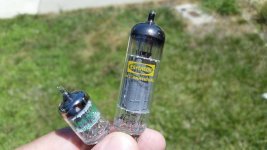
Looks like the usual beamer 6HB6s. They should use them for lottery tickets. All look the same, some pay off.
Hello All,
I received 3 dozen of these valves this past week. They do have a look about them.
I know that you are applying this tube as push-pull AB operation. My application will be as a Single End Triode headphone amplifier. The operating bias will be selected for low noise. I am assuming that this will not be even close to maximum plate dissipation. Remembering that output distortion is proportional to output power driving a pair of headphones at the milliwatt level will be at vanishing levels of distortion.
Thoughts?
DT
Even in SE mode is good to select them for using the most equal specimens, due to triode mode gain (if you use an cathode bias, is very easy to match; equal bias means not much distant triode gain I believe).Hello All,
I received 3 dozen of these valves this past week. They do have a look about them.
I know that you are applying this tube as push-pull AB operation. My application will be as a Single End Triode headphone amplifier. The operating bias will be selected for low noise. I am assuming that this will not be even close to maximum plate dissipation. Remembering that output distortion is proportional to output power driving a pair of headphones at the milliwatt level will be at vanishing levels of distortion.
Thoughts?
DT
- Status
- Not open for further replies.
- Home
- Amplifiers
- Tubes / Valves
- 6HB6 as finals