Something is very odd with your voltage readings, how are you measuring the grid voltage? Where is the -2.87V measured from? Also, the screen current is separate from the plate current, they are added together at the cathode.
The plate current is who make core saturation, but if screen current is far different in 2 valves, indicate bad pair matching or some trouble.
Maybe he is measuring the G1 directly with voltage loss from grid biasing resistor. Best is measure before the bias resistors.(
Maybe he is measuring the G1 directly with voltage loss from grid biasing resistor. Best is measure before the bias resistors.(
The plate current is who make core saturation, but if screen current is far different in 2 valves, indicate bad pair matching or some trouble.
Maybe he is measuring the G1 directly with voltage loss from grid biasing resistor. Best is measure before the bias resistors.(
measure bais supply voltage -3.07
skal
Ok lads ,the plate voltage was at 380v all this time , so now i have reduce it to 250vdc regulated for now ..
New measurements..
bIAS supply voltage -3.00
plate 250vdc @ v1@33ma v2@33ma
screen 250dc
total cathode current v1 and v2 and screen grid 71ma
regards
skal
New measurements..
bIAS supply voltage -3.00
plate 250vdc @ v1@33ma v2@33ma
screen 250dc
total cathode current v1 and v2 and screen grid 71ma
regards
skal
Last edited:
Hmm, that does not come even close to the datasheet, at -3V bias, the plate current should be around 60mA per tube, not 33mA.bIAS supply voltage -3.00
plate 250vdc @ v1@33ma v2@33ma
screen 250dc
total cathode current v1 and v2 and screen grid 71ma
Hmm, that does not come even close to the datasheet, at -3V bias, the plate current should be around 60mA per tube, not 33mA.
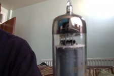
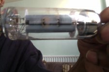
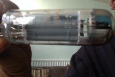
so what you thinking , these are not 6hb6s , i can post a pic if that will help
cheers
skal
May be... but first, please make sure that all the voltage and current readings are correct, is the meter calibrated? You can measure a battery to make sure it is reading properly.
Well, it is reading about 10% high, which makes the -3V bias even more puzzling, please post a pic of the tube, may be smoking-amp can tell us if it is genuine or not.
Well, it is reading about 10% high, which makes the -3V bias even more puzzling, please post a pic of the tube, may be smoking-amp can tell us if it is genuine or not.
ok here
Attachments
Most 1V5 batteries have 1.6 to 1.7V when new/few use and unloaded.Well, it is reading about 10% high, which makes the -3V bias even more puzzling, please post a pic of the tube, may be smoking-amp can tell us if it is genuine or not.
Perhaps these 6HB6 is really very spreading in practice or have "defective" emission like smoking-amp have reported with a "low-gm" 6HB6 in post #44.
You are right, in any case, it was not off that much to make the other readings invalid. So the low plate current are for real, almost 50% less, no wonder the tubes did not red-plate when skal cranked them up before - the dissipation was still pretty low.
You are right, in any case, it was not off that much to make the other readings invalid. So the low plate current are for real, almost 50% less, no wonder the tubes did not red-plate when skal cranked them up before - the dissipation was still pretty low.
Remember the plate is regulated, would this effect results?
so what does this mean, should i carry on with this tube and adjust the bias for a bit glow

There is an easy test to see if the valves are with low emission or if it is only characteristics spread, if you have the pre stages already built: measuring the output power with sine wave. It should be more than 10Wrms at the output to consider these valves suitable to use. If this output power is reached, you no need to care about the odd/strange bias anymore...
There is an easy test to see if the valves are with low emission or if it is only characteristics spread, if you have the pre stages already built: measuring the output power with sine wave. It should be more than 10Wrms at the output to consider these valves suitable to use. If this output power is reached, you no need to care about the odd/strange bias anymore...
how much af voltage signal do i need to put in the grid ? to get the 10wrms?
Well not sure if you can get 10W, since the bias is only at -3V now, in any case, you can try 6Vp-p or 2.12Vrms per tube and see what you get on the output of the transformer, I trust that you have an OPT and a dummy load?how much af voltage signal do i need to put in the grid ? to get the 10wrms?
The skal tube Pics look like the usual beam type 6HB6.
-------------------------------
RE: DualTriode
Those earlier curves were taken some while back, and I had put a tube on the tracer again to get the scale readings. The triode curve set was estimated at 1.5V / g1 step.
-----
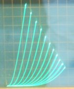
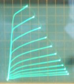
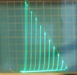
I've now put a GE 6HB6 (beam type) tube on the tracer again today to get more accurate settings for the same tube in triode and pentode mode. Yes, triode has g3 to cathode, and g2 to plate. Pentode has g3 to cathode. Plate V is 50 V/div Horizontal from 0 at axis and Plate current is 20 mA/div Vertical from 0 at axis.
Note that this is a more typical 6HB6 triode curve set with more obvious compressed curves at HV. (The earlier triode curve set was a really good one with less compression. )
Triode g1 stepping 1.5 V
Pentode g1 stepping 0.5 V, and g2 at 120 V
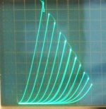
I've included the earlier Schade configured 6HB6 for comparison, with an about 3.5 gain R Fdbk network, don't have info on the drive setting on the tracer, but can derive that approximately from the gain and plate V.
Schade curves have same 50V/div Horiz and 20 mA/div Vert.
and also the 4th pic is the earlier 6HB6 triode curves for comparison.
-------------------------------
RE: DualTriode
Those earlier curves were taken some while back, and I had put a tube on the tracer again to get the scale readings. The triode curve set was estimated at 1.5V / g1 step.
-----
I've now put a GE 6HB6 (beam type) tube on the tracer again today to get more accurate settings for the same tube in triode and pentode mode. Yes, triode has g3 to cathode, and g2 to plate. Pentode has g3 to cathode. Plate V is 50 V/div Horizontal from 0 at axis and Plate current is 20 mA/div Vertical from 0 at axis.
Note that this is a more typical 6HB6 triode curve set with more obvious compressed curves at HV. (The earlier triode curve set was a really good one with less compression. )
Triode g1 stepping 1.5 V
Pentode g1 stepping 0.5 V, and g2 at 120 V
I've included the earlier Schade configured 6HB6 for comparison, with an about 3.5 gain R Fdbk network, don't have info on the drive setting on the tracer, but can derive that approximately from the gain and plate V.
Schade curves have same 50V/div Horiz and 20 mA/div Vert.
and also the 4th pic is the earlier 6HB6 triode curves for comparison.
Attachments
Last edited:
- Status
- Not open for further replies.
- Home
- Amplifiers
- Tubes / Valves
- 6HB6 as finals