I'm looking for data on the russian 6H6pi, like curves. Are 6H6P and 6H6N faulty names for the same tube?
It must swing 150 to 180 volts in the grid of a 6C41C, SRPP seemed a good choice, not?
Got one hooked up at 3mA but I guess this would be out of the linear region...
Sounds somewhat like the loudness switch is pressed")
otoh ... this might come from the high impedance PSU as I measured >1V AC on the cathode.
Impressive bassnotes from the EV15B though
It must swing 150 to 180 volts in the grid of a 6C41C, SRPP seemed a good choice, not?
An externally hosted image should be here but it was not working when we last tested it.
Got one hooked up at 3mA but I guess this would be out of the linear region...
Sounds somewhat like the loudness switch is pressed
otoh ... this might come from the high impedance PSU as I measured >1V AC on the cathode.
Impressive bassnotes from the EV15B though
An externally hosted image should be here but it was not working when we last tested it.
I would suggest much higher currents for the 6N6P. I use them at around 20mA anode current and 4.4V bias voltage. In the lower half of the tube you could also use two green LED’s in series for bias (giving around 4.4V bias @ 20mA).
Sound quality can further be enhanced by bypassing the LED’s with HQ capacitors. I like tantalum capacitors very much in that position.
Peter
Sound quality can further be enhanced by bypassing the LED’s with HQ capacitors. I like tantalum capacitors very much in that position.
Peter
Hi Peter,
Raising the current to 9mA did the 6H6pi good. I will investigate your advice but Vgk must be at least 7V as my pre has highish output voltage. The current situation:
In the meantime I got data on the 6C41C and lowered the grid leak resistor (200K max) to 150K ohm. The SRPP likes it as distortion is noticeably lower. Optimizing it is new to me so I'm reading MerlinB's article. Good source.
I'm trying to determine the exact load for the SRPP.
Taken from the 'Basic Data Electrical Parameters' 6C41C is specified for input capacitance between 5 and 17pF and for mutual conductance anywhere between 12 and 26mA/V. What impedance will be parallel to the load resistor?
Raising the current to 9mA did the 6H6pi good. I will investigate your advice but Vgk must be at least 7V as my pre has highish output voltage. The current situation:
An externally hosted image should be here but it was not working when we last tested it.
In the meantime I got data on the 6C41C and lowered the grid leak resistor (200K max) to 150K ohm. The SRPP likes it as distortion is noticeably lower. Optimizing it is new to me so I'm reading MerlinB's article. Good source.
I'm trying to determine the exact load for the SRPP.
Taken from the 'Basic Data Electrical Parameters' 6C41C is specified for input capacitance between 5 and 17pF and for mutual conductance anywhere between 12 and 26mA/V. What impedance will be parallel to the load resistor?
6C41C properties
All (four) 6C41C power triodes I own measure south of this graphic. Is there a smarter method to obtain ra than inputting say 10Vrms into its grid and measuring voltagedrop over a test resistor in the cathode?
My actual operating point: Va-c= 298-74= 224V, Iq= 74V/750 ohm= 98mA.
The steepness of the green line in this graphic suggests a ra of 26V over 140mA= 186 ohm and a gm of 5.4mA/V. What can be made of Cmiller and how does it load our SRPP?
The whole thing of getting the numbers right depends of course on some trustworthy data and formulae but when it's whetfingering all over the place one could better use its floppies, or perhaps borrow an old HP 334A and study the manual
An externally hosted image should be here but it was not working when we last tested it.
Yes, noticed that one. I've evened out the scales (purple):
An externally hosted image should be here but it was not working when we last tested it.
Thanks Walter, seems I'm stuck then, with the available power supply voltage for the SRPP.
WRT SRPP driving miller capacitance (besides the grid leak resistor) it sees a falling impedance with frequency. The stage could be optimised for a 'worst case scenario' but the distortion of a not optimal tuned SRPP is already of a much smaller magnitude than that of the SE output stage.
WRT SRPP driving miller capacitance (besides the grid leak resistor) it sees a falling impedance with frequency. The stage could be optimised for a 'worst case scenario' but the distortion of a not optimal tuned SRPP is already of a much smaller magnitude than that of the SE output stage.
Doing the math with the formulas presented by M. Blencowe, I adjusted the load resistance to the (for practical reasons) chosen 690 ohm kathode resistors.
Rload = (mu*Rk1,2 - ra) / 2 = (22*690 -1800) / 2 = 6690 ohm
Quiescent current Iq = HT / (2*ra + 2*mu*Rk) = 285 / 2*1800 + 2*22*690 = 8.4mA
Max undist voltage swing = 4* 8.4mA = 33.6 in 6690 ohm = 225Vpp or 80Vrms
Output impedance ca 600 ohm.
Even when optimising was an theoretical effort, the amplifier sounds finer with the lowered grid leak. Worth the trouble I'd say.
It's in anti phase to the output tube, wasn't it? That way lowering 3H would not harm.
I've just begon voicing but it has potential. First a smaller coupling cap as output impedance of the SRPP is that low. Bold bass response from that 150VA output, quite different to the AD1 sound I'd say
I've just begon voicing but it has potential. First a smaller coupling cap as output impedance of the SRPP is that low. Bold bass response from that 150VA output, quite different to the AD1 sound I'd say
To my surprise as I was looking to use this valve in an OTL headphone amp, found it was not very linear:
http://www.bartola.co.uk/valves/2012/06/17/thd-benchmark/
Close to the top chart of the worst ones am afraid, however this is just a THD test...
Cheers,
Ale
http://www.bartola.co.uk/valves/2012/06/17/thd-benchmark/
Close to the top chart of the worst ones am afraid, however this is just a THD test...
Cheers,
Ale
Well, the charm is in the topology as SRPP operates in class A only. Under condition that both triodes contribute equally to the load, all even harmonics (not only 2H) cancel, resulting in minimum THD. This deep null is obtainable for a fixed load only and it does not clip pleasantly.
To my surprise as I was looking to use this valve in an OTL headphone amp, found it was not very linear:
So was I.

What circuit were you considering?
jeff
It's in anti phase to the output tube, wasn't it?
That is correct. But this mostly affect 2H. Without distortion cancellation this circuit and many other would have gross distortion.
Well, the charm is in the topology as SRPP operates in class A only. Under condition that both triodes contribute equally to the load, all even harmonics (not only 2H) cancel, resulting in minimum THD. This deep null is obtainable for a fixed load only and it does not clip pleasantly.
The lack of charm is that the less pleasant uneven harmonics are worse than for other topologies. This can be bettered going mu-follower instead where gain will also be higher. You unfortunately need somewhat higher B+. If using sand as upper mu-element or a "iron-follower", B+ is OK.
Last edited:
It has, the loudness is still onThat is correct. But this mostly affect 2H. Without distortion cancellation this circuit and many other would have gross distortion.
The 300V HT is too low to drive the SRPP with more current and the available power tranny was a design parameter, unfortunately.
I thought about feedback for cancellation. If my numbers are right there's a 50Vpp margin for driving the power triode to full output. That would make NFB over the OPT to the driver input possible. Things seem to get too complicated to feed the anode of the power tube back to another node of the SRPP and still maintain some sort of even push pull operation..
Yet another possibility to lower or substantially diminish uneven harmonics would be a like-drive-like situation with a second SRPP. Anyone tried this? That would leave us with plenty of gain for overall feedback
The lack of charm is that the less pleasant uneven harmonics are worse than for other topologies. This can be bettered going mu-follower instead where gain will also be higher. You unfortunately need somewhat higher B+. If using sand as upper mu-element or a "iron-follower", B+ is OK.
I was thinking about a Beta follower with a BC560, is that what you meant by iron follower, or just an interstage?
Perhaps I'll have another look at a penthode driver and see with what I can come away with driving that miller capacitance. I married a C3G happily to a 2A3 but that's an easy load
Last edited:
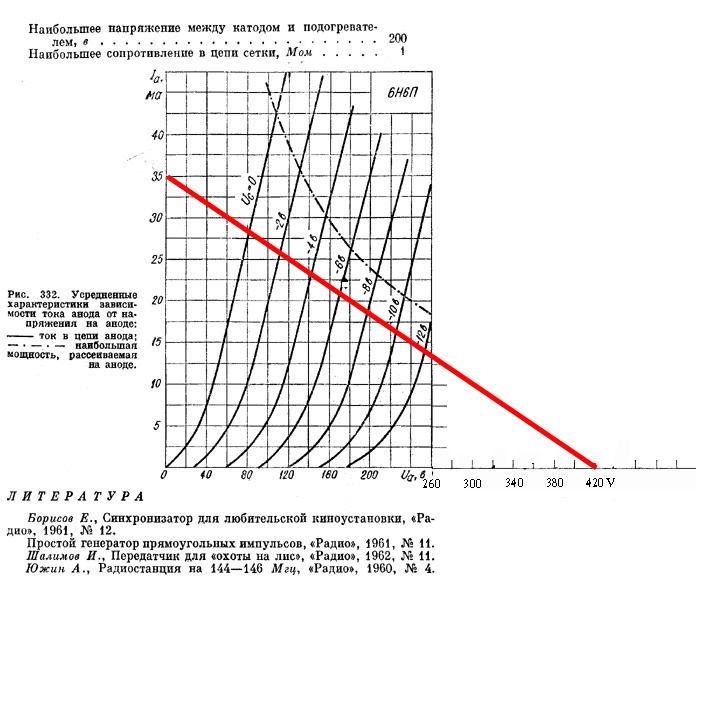
Ea is NOT Ua
Ea is a power supply voltage
Ua is a plate voltage
Under 420 V power supply and 12 k anode load the plate dissipation is less than maximum threshold for this tube (dashed curve).
Just such a mode is preferable to drive 'heavy" output triodes (no impact of their input impedance due to Miller’s capacity ).
Taking into account the outstanding linearity of 6N6P one can chose the bias point here in a rather wide range.
Sincerely yours.
Has anybody tested the harmonic spectrum of 6H6pi in SRPP?
- Status
- This old topic is closed. If you want to reopen this topic, contact a moderator using the "Report Post" button.
- Home
- Amplifiers
- Tubes / Valves
- 6H6pi curves available?