Hi,
Just finished building this amp. This tube is the compactron sister of 6em7 and according to GE manual from 1964 they are similar.
Anyway, looking over the net I have seen very little use of this tube though this amp sounds incredibly good.
What is your experience?
BR
Glass painter
Just finished building this amp. This tube is the compactron sister of 6em7 and according to GE manual from 1964 they are similar.
Anyway, looking over the net I have seen very little use of this tube though this amp sounds incredibly good.
What is your experience?
BR
Glass painter
Attachments
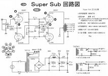
Why in the world shunt a power supply choke with a 2.2uF cap? they just bypassed the choke with ripple.
"Why in the world shunt a power supply choke with a 2.2uF cap? "
Must be one of those 120 Hz resonant traps. I don't see the value of the 1st inductor shown to check that. Then it needs the second filter section to remove all the other frequencies. Except the B+ is coming off the 1st section? Well, could be better for sure.
Must be one of those 120 Hz resonant traps. I don't see the value of the 1st inductor shown to check that. Then it needs the second filter section to remove all the other frequencies. Except the B+ is coming off the 1st section? Well, could be better for sure.
I did not build the PS this way but I have read somewhere that the cap is forming a filter with the choke further reducing hum and noise on a crowded chassis.
Since I separate the PS on all my builds to another smaller chassis, a simple RCRC is all is needed for a super silent amp.
Since I separate the PS on all my builds to another smaller chassis, a simple RCRC is all is needed for a super silent amp.
The 2.2 uF is a "trick" that is usually overlooked, and misunderstood.
This is a special case of a capacitor input power supply (this supply has a 220uF cap input).
A 2.2uF cap will resonate with 0.8 Henrys at 120 Hz.
A 2.2 uF cap will resonate with 1.15 Henrys at 100Hz.
120Hz or 100Hz is the ripple frequency of the full wave rectifier in this circuit.
A parallel circuit of 2.2uF and 0.8H or 1.15H will be a very high impedance to the ripple frequency. It will attenuate the ripple by a very large amount.
Without the 2.2uf, it would require a much higher inductance to get the same reduction of ripple.
A 5H, 10H, or 20H choke is more expensive, larger, and heavier than a 0.8 or 1.15H choke.
Another clue about this supply is that the 2.2uF is not an electrolytic cap.
But do Not try this trick with a Choke Input power supply configuration.
It may cause shorted diodes, shorted cap, or shorted choke turns.
The voltage rise in a Resonant Choke Input supply is Very large.
Doesn't an RCPS omit the first capacitor? It seems to me that they have hybridized a CLC with a RCPS.
funny, I'm so used to putting together my own power supplies I didn't even notice the 2.2uF capacitor across the choke
curious, what output transformer did you use? I have a bunch of 13EM7's, night make a fun project some time
curious, what output transformer did you use? I have a bunch of 13EM7's, night make a fun project some time
I have used for this specific project Japanese mid fi transformers name Ichikawa trans. ITPP-10w is the model. very good value for money but still not Tamura Hashimoto or Tango.
This is why I was so surprised listening to the amp after finishing it. I have listened to this transformers in several other builds, they sound nice but with this topology and this tube they sound very good.
I have Hashimoto units as well and plan to use them on my next build utilizing the same topology and tubes as I have more of them (this one was built for a friend) - let you know the results when I am done.
Some caution is warranted. I suggest you read all of this.
A detailed article on resonant choke supplies may be found here: www.qsl.net/i0jx/supply.html
One might well ask why every supply doesn't use a resonant choke. The reason is that a resonant choke only filters a specific frequency, typically 120 Hz or 100 Hz depending upon the mains frequency (2x base frequency).
Because the notch is narrow a resonant choke readily passes other frequencies and adds higher-order harmonics, albeit at lower magnitude. Since most of the noise is twice the mains frequency, the resonant choke is reportedly a good way to remove it as long as additional filtering is performed to remove the ripple at the non-resonant frequencies.
Filtering also depends upon load.
As a result, the power supply above described does not properly filter other harmonics and ripple current. It consequently is far less clean than a non-resonant supply, and does not work the way one might think.
The resonant frequency (f0) is given by:
f0 = 1 / (2 × Pi × sqrt(L × C))
Given L and f0, C is determined as:
C = 1 / (2 × Pi × L × f0)^2
Note: L in Henries, C in Farads, and f0 is in Hz.
You may easily determine how permeable the capacitor or choke (inductor) are at any given frequency:
Inductive Reactance (XL) = 2 × Pi × f × L
Capacitive Reactance (XC) = 1 / (2 × Pi × f ×
C)
Note: L in Henries, C in Farads, and f is in Hz.
Resonant choke supplies can be very dangerous.
The high voltage across the inductor has 120 Hz or higher order components and it may be boosted to several times the expected value. This can blow up the capacitor if it is not properly rated, can fry the power supply, the amplifier, or you.
This voltage is not readily discharged when the power supply is turned off. This is why a bleeder resistor is required.
Tinkering with high-voltage supplies when one does not understand the ramifications can result in injury, disfigurement, or death.
Someone with knowledge of resonant choke supplies is requested to add it here.
Motorola used the resonant trap trick in several of their vacuum tube base station transmitter power supplies. The ones I had were 1500 volt 1/2 amp units. The cap across the inductor was an oil filled unit rated at 6000 volts, yes a parallel resonant circuit can generate a lot of voltage. The cap will however be discharged by the DCR of the choke when the supply is switched off and all the ringing stops. The bleeder is insurance against an open choke.
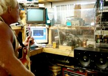
This type of power supply does require some specialized testing, and as I found out works well when there is a constant load like the class A SE design posted. It can be driven into convulsions by a load drawing huge peaks on bass notes below its tuned resonance. In my case it was an 833A in SE driven to clipping by a blonde with a guitar preamp set on KILL, and only resulted in the 15 amp line breaker being tripped as the house lights started blinking.
This type of power supply does require some specialized testing, and as I found out works well when there is a constant load like the class A SE design posted. It can be driven into convulsions by a load drawing huge peaks on bass notes below its tuned resonance. In my case it was an 833A in SE driven to clipping by a blonde with a guitar preamp set on KILL, and only resulted in the 15 amp line breaker being tripped as the house lights started blinking.
It still seems to me that the schematic presented in the first post is not a Resonant Choke Power Supply.
It has a capacitor before the inductor.
An RCPS should not have the capacitor before the inductor just as an Input Choke Power Supply has no capacitor before the inductor.
It has a capacitor before the inductor.
An RCPS should not have the capacitor before the inductor just as an Input Choke Power Supply has no capacitor before the inductor.
The cap across the inductor was an oil filled unit rated at 6000 volts, yes a parallel resonant circuit can generate a lot of voltage. The cap will however be discharged by the DCR of the choke when the supply is switched off and all the ringing stops. The bleeder is insurance against an open choke.
Without the bleeder what's the time constant on that discharge? The inductor also doesn't have any flyback diode to get rid of the now-increased inductive kick. Should have mentioned that, too.
It can be driven into convulsions by a load drawing huge peaks on bass notes below its tuned resonance. In my case it was an 833A in SE driven to clipping by a blonde with a guitar preamp set on KILL, and only resulted in the 15 amp line breaker being tripped as the house lights started blinking.
Nice story. I'm not surprised.
That variable load is a ginormous pile of low-frequency ripple, spread out below a few hundred Hz, and the power supply is going to need some filtering ability to absorb that. By tuning the choke the Pi filter can't readily absorb it. I would also expect ringing in the power transformer from that stimulus.
the schematic presented in the first post is not a Resonant....An RCPS should not have the capacitor before the inductor
It would seem that the huge caps on either side of the LC would swamp the C that is across the inductor. That may or may not be the case here, I guess it would be prudent to simulate the whole thing before building this. The RCPS's that I had used a much smaller input cap. 4uF maybe, I don't remember and can't read the numbers in my old pictures.
what's the time constant on that discharge?
I made the assumption that there is still a resistive bleeder across the output of the supply (pretty much mandatory), so there is a path for current to flow from the input filter cap toward the bleeder when the line input is switched off. There will be some ringing in the LC circuit as the cap discharges through it, created by the drop off in current through the inductor. The Motorola power supplies that I had did have an input cap, as does this circuit, however the values were much smaller since it expected either no load, (transmitter on, but not transmitting) or a full load (transmitter cranking out 120 watts at 450 MHz). If there was no input filter cap, there must be a bleeder across the LC or the diodes would likely be blown on power off.
ginormous pile of low-frequency ripple, spread out below a few hundred Hz
The breaker blower was single notes on the guitar in the sub 100Hz range. I even tried to time the notes to coincide with the blinking of the lights until I popped the breaker. The test amp still worked, so I did it again.
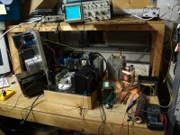
I used the Motorola power supply to jury rig together a test amp to analyze a sample OPT. As is my normal custom, I "test" my designs far beyond what a normal user would, or should do to them. In all cases my amps get to eat some of my lousy, but loud guitar playing. I have found and fixed a few weak points in a few designs this way. The 10 uF 7.5 KV cap from an old defibrillator was added across the output to tame some of the misbehavior.
Since this amp ran on an instantly lethal power supply, I had a 1/4 inch Lexan shield between me and the amp(and a fire extinguisher at my feet) for all testing. It was removed for one picture taken from several feet away.
Attachments

maybe i'm in the minority here, but I think this is being blown out of proportion. Here's the 100+ year old electronic formula to provide guidance:
VPP-internal = Vripple-input √( Q )
However, if you do a little napkin calculation based on E=IR Ohm's Law, we get some easily derived total current draws.
The 10 kΩ resistor between power supply B₁ and B₂ and its ΔV of 44 volts nominal yields 4.4 ma of current drawn by B₂ load. Likewise, if you look at the 470 Ω cathode-bias resistor of the output stage and its ΔV of +36 volts, we get 74.5 ma of current drawn by the final. 74.5 + 4.4 ≈ 79 ma drawn by both. Then, looking at the LC buck, noting the ΔV of 13 volts across it … with E=IR, R=E/I R ≈ 13 ÷ 0.079 ≈ 160 Ω. (Higher than I would have thought! Must be a smallish inductor.)
Now. We have an approximation for the RL internal resistance. Let's see what level of ripple will be fed into it.
ΔVC … between T=0 and T=¹/₁₂₀ sec (8.33 ms) is easy to estimate. Remembering that dV/dt ≈ ∫( i(t) / C ) dt, or for reasonable approximation over small dt …
ΔVC ≈ i/C • Δt
ΔVC ≈ 79 ma ÷ 220 μF × 8.33 msec
ΔVC ≈ 0.079 ÷ 0.000220 × 0.0833
ΔVC ≈ 30 volts (it'll actually be less)
So…
VPP-internal = Vripple-input √( Q )
VPP-internal ≈ 30 √( 50 )
VPP-internal ≈ 210 volts
Well. There you are. Use a 500 volt or 750 volt self healing oil cap, and you mostly should be good.
The talk about a flyback diode is a bit misadjusted.
And questioning whether the buck cap will be discharged is also a non-starter.
However, it is also the case that the whole power supply should have a shutdown bleeder resistor added (in parallel) to the INPUT side of the buck reactor, of about 40 kΩ at 5 watts. Safety first!
GoatGuy
VPP-internal = Vripple-input √( Q )
However, if you do a little napkin calculation based on E=IR Ohm's Law, we get some easily derived total current draws.
The 10 kΩ resistor between power supply B₁ and B₂ and its ΔV of 44 volts nominal yields 4.4 ma of current drawn by B₂ load. Likewise, if you look at the 470 Ω cathode-bias resistor of the output stage and its ΔV of +36 volts, we get 74.5 ma of current drawn by the final. 74.5 + 4.4 ≈ 79 ma drawn by both. Then, looking at the LC buck, noting the ΔV of 13 volts across it … with E=IR, R=E/I R ≈ 13 ÷ 0.079 ≈ 160 Ω. (Higher than I would have thought! Must be a smallish inductor.)
Now. We have an approximation for the RL internal resistance. Let's see what level of ripple will be fed into it.
ΔVC … between T=0 and T=¹/₁₂₀ sec (8.33 ms) is easy to estimate. Remembering that dV/dt ≈ ∫( i(t) / C ) dt, or for reasonable approximation over small dt …
ΔVC ≈ i/C • Δt
ΔVC ≈ 79 ma ÷ 220 μF × 8.33 msec
ΔVC ≈ 0.079 ÷ 0.000220 × 0.0833
ΔVC ≈ 30 volts (it'll actually be less)
So…
VPP-internal = Vripple-input √( Q )
VPP-internal ≈ 30 √( 50 )
VPP-internal ≈ 210 volts
Well. There you are. Use a 500 volt or 750 volt self healing oil cap, and you mostly should be good.
The talk about a flyback diode is a bit misadjusted.
And questioning whether the buck cap will be discharged is also a non-starter.
However, it is also the case that the whole power supply should have a shutdown bleeder resistor added (in parallel) to the INPUT side of the buck reactor, of about 40 kΩ at 5 watts. Safety first!
GoatGuy
It would seem that the huge caps on either side of the LC would swamp the C that is across the inductor. That may or may not be the case here, I guess it would be prudent to simulate the whole thing before building this.
The big issue with resonant chokes is that small changes have disproportionate effects, and the consequences of the narrow notch are not well understood by the people using them. Most haven't simulated the ripple or tried to measure it.
So, no argument there, always a good idea to simulate.
As is my normal custom, I "test" my designs far beyond what a normal user would, or should do to them. In all cases my amps get to eat some of my lousy, but loud guitar playing. I have found and fixed a few weak points in a few designs this way. The 10 uF 7.5 KV cap from an old defibrillator was added across the output to tame some of the misbehavior.
Wow.
My hat is off to you. I have never heard the words "defibrillator" and "guitar amplifier" in the same sentence unless it involved the infamous "death capacitor" and a live microphone case.
Since this amp ran on an instantly lethal power supply, I had a 1/4 inch Lexan shield between me and the amp(and a fire extinguisher at my feet) for all testing. It was removed for one picture taken from several feet away.
Again, beholding much awesomeness.
Wow.
Is that a transmitting tube?
I have a pair of small triodes that a old engineer gave me saying, here, you like tubes, go build a single-ended amplifier with these. I then discovered they needed a few kV and were, as you noted, instantly lethal.
In fact, just reading the datasheet and imagining the power supply made my heart go into a-fib.
Non-linear, too, but if they ran at 200 V instead of 2,000 V that wouldn't have stopped me. It was the arcing in air part of the power supply, and the potential for being instantly killed dead, however, that gave me serious pause. Today my jurisdiction ends here.
Is that a transmitting tube?
Yes, they were common in post WWII AM radio transmitters. The RCA and Gates transmitters used 4 of these, 2 were the RF power output stage, and the other two were the modulator. The transmitters were conservatively rated at 500 watts. It was common for these to run for years before needing service. The 833A data sheet is enclosed.....they will eat 4000 volts!
I got several of these tubes for free, and I had a custom OPT wound for a possible big A$$ HiFi amp, but the transformer wasn't quite good enough. I put this test amp together for the purpose of testing the OPT. The amp delivered 200 watts RMS, and as you saw it survived a bunch of abuse. The guitar test was heard from 2 blocks away. I took the test amp apart after about 10 days since it took up my whole work bench and had no practical use. I gave away the power supplies since they weighed about 80 pounds each (I had 3), but kept the tubes and the OPT just in case I decided to build a rather impractical guitar amp.....it's been about 8 years and I haven't built it yet.
Another forum builder with a bigger budget has made a rather nice amp using the same tube. It is detailed here:
http://www.diyaudio.com/forums/tube...-crisis-my-833c-amp-build.html?highlight=833A
Coincidentally I was "retired" about 3 years ago from my 41 year career as a transmitter designer at Motorola, no tube stuff though. I have a bit more free time now, so........
Attachments
- Status
- Not open for further replies.
- Home
- Amplifiers
- Tubes / Valves
- 6FM7 pp amp