Just kanged together another amp. This one uses 6F12P for gain and phase splitting duty, and 6P43P in triode connection.
It also uses toroidal power transformers as OPTs like all of my other designs... The total build price is less than $300CAD with a chassis etc.
The output stage is biased at 270V/56ma which slightly exceeds the dissipation, but like George of Tubelab I'm willing to push the tubes a little harder than specified.
Thoughs?
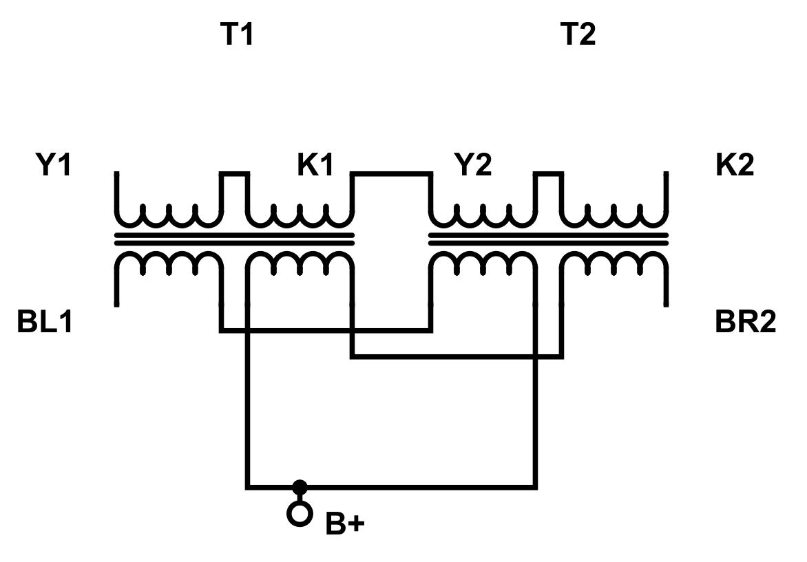
EDIT: Don't use one OPT, use two... Search for "interleaved toroidal
It also uses toroidal power transformers as OPTs like all of my other designs... The total build price is less than $300CAD with a chassis etc.
The output stage is biased at 270V/56ma which slightly exceeds the dissipation, but like George of Tubelab I'm willing to push the tubes a little harder than specified.
Thoughs?
EDIT: Don't use one OPT, use two... Search for "interleaved toroidal
Attachments
Last edited:
How'd I miss this?
Looks fun. I've been meaning to grab a few 6F12P to play with. Seems like a good little concertina tube.
On an interesting note, I tried out some of the twenty one 6P43P-E that I picked up in an amplifier that I'm prototyping just last night. I did garter bias with 500R resistors each, 2200uF cathode bypass caps, 160-250 volt adjustable screen supply (started it at the low end to be safe) and a 300 volt supply. Within a minute of warmup each of the tubes were redplating! I measured 59 volts at the cathodes (29.5 volts across each cathode resistor) for 59mA through each tube at 191 volts for 11.26W dissipation. The power supply had sagged to 250 volts, and I blew one of the 50 volt rated bypass caps. Out of curiosity I threw in a set of RCA EL86/6CW5 ("made in great britain" marked) and the power supply went back to 300 volts, I adjusted the screen supply to 185 volts, and got 16 volts across each 500R resistor, for 32mA, 268 volts across the tube, 8.576W dissipation. Much, much better. might be good to switch to 400R for a smidge more current.
I'm not using any grid stoppers at the output sockets. Could this have contributed, or do these suckers just not like higher voltages? I went a bit higher on the cathode resistors on purpose, just to be a bit conservative on dissipation/biasing. Seeing you have them triode connected seems like they should be doing the same thing, but your cathodes are CCS biased, although i suppose that really shouldn't matter...
I dunno, I haven't tried them as pentodes, only triode connection. Always a good idea for grid stoppers, it's likely there was an RF oscillation robbing the power. I use 1k on power tubes (unless they are KT88 style, then I use 10k) and 300R on signal tubes. The CCS would just climb in voltage like the resistor did. Remember a CCS isn't really a current source, but a current limiter. I have roughly 30V on the CCS leaving 270V*56ma for 15W Pd. Also the schematic calls for a 380V boost, but I'm using 120V -> delon doubler for 300V. Also I've started using more gNFB as you can probably tell by the NFB network. This amp will require an input of 4V+ for full output as my other designs, but my line amp will output over 20V.
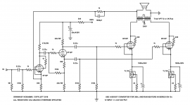
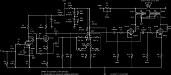
So I figured I'd share the final schematic for this amp. I've included a driver to improve things. This amp sounds excellent, and it's loud. It also doesn't require 4V input anymore, which is a bonus for a lot of you.
Please note: the 12k dropping resistor should be 5W, and the 2K dropping resistor also 5W. These are not marked as such, but a 1/2W resistor will quickly fail.
So I figured I'd share the final schematic for this amp. I've included a driver to improve things. This amp sounds excellent, and it's loud. It also doesn't require 4V input anymore, which is a bonus for a lot of you.
FYI for those needing a universal PA/VI/Driver, just rip it from this. It will swing trioded 6P45S tube to their output (112W). If you don't need 100+V swings, you can lower the B+ to 400V or so, but nix the 12k dropper on the VA/PI.
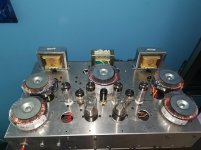
And here's a picture of the amp as built (in a scrap chassis).
So I figured I'd share the final schematic for this amp. I've included a driver to improve things. This amp sounds excellent, and it's loud. It also doesn't require 4V input anymore, which is a bonus for a lot of you.
Please note: the 12k dropping resistor should be 5W, and the 2K dropping resistor also 5W. These are not marked as such, but a 1/2W resistor will quickly fail.
So I figured I'd share the final schematic for this amp. I've included a driver to improve things. This amp sounds excellent, and it's loud. It also doesn't require 4V input anymore, which is a bonus for a lot of you.
FYI for those needing a universal PA/VI/Driver, just rip it from this. It will swing trioded 6P45S tube to their output (112W). If you don't need 100+V swings, you can lower the B+ to 400V or so, but nix the 12k dropper on the VA/PI.
And here's a picture of the amp as built (in a scrap chassis).
Attachments
too many caps in the signal path,(just me) how is the stability?
the 6F12P is a fine tube, the 6LQ8 i think will do fine in that amp too..
the 6LQ8 still sells for a dollar at Stan's....last time i looked....
the 6F12P is a fine tube, the 6LQ8 i think will do fine in that amp too..
the 6LQ8 still sells for a dollar at Stan's....last time i looked....
And here's a picture of the amp as built (in a scrap chassis).
Hi all. My first post - it's really great to join here.
I'm scavenging ideas nowdays for my first build and got my eyes on some 6F12P and 6N2P + 6P1P for power (heard many great things about this power tetrode)!
Wanted to ask you kodabmx, why is that C7 such high value on that cathode bias of the 6F12P pentode section ?
Thanks!
too many caps in the signal path,(just me...
Since its DIY one could probably omit the first input cap if you know your source has no DC right? For a commercial product you'd probably need it there because you don't know what is plugged into it. Very few music sources these days have any DC component. I might be all wrong but why have C1 unless there is a need to block some DC?
You could omit C6, and maybe DC couple the concertina to the preceding plate to omit C2, but you will lose a bit of headroom by reducing the voltage across the concertina. At such high supply voltage it may work though.
For the amount of work involved in swinging all that voltage I would have used the front end on a higher power output tube, probably a nice sweep tube in pentode mode 🙂 (in fact, I'm figuring out a similar schematic to do a 12AV5GA build at some point...)
For the amount of work involved in swinging all that voltage I would have used the front end on a higher power output tube, probably a nice sweep tube in pentode mode 🙂 (in fact, I'm figuring out a similar schematic to do a 12AV5GA build at some point...)
The front end is universal. Indeed it's the same as on my monobloc... It also allows a LOT of gNFB if the OPTs are up to it.
C7 is so high because why not? And I had them..
You could omit the input cap. I put it there just in case.
6P1P is a 6V6 in a 9 pin bottle basically (slightly lower Pd). Excellent tube and quite linear in triode connection. 6P43P just spanks it though 😛
C7 is so high because why not? And I had them..
You could omit the input cap. I put it there just in case.
6P1P is a 6V6 in a 9 pin bottle basically (slightly lower Pd). Excellent tube and quite linear in triode connection. 6P43P just spanks it though 😛
News:
I've reverted the gNFB network to 2k||3000pf. I also sorted out a miswire that was killing treble. The secondaries were in series, but I had the order of the secondaries backwards.
If you use this method of connecting Triad mains transformers as OPTs, here's the wiring code
Primaries:
Blue #1 - Plate 1 (Inverted)
Grey #1 - Blue #2
Brown #1 - Purple #2
Purple #1 - Grey #2
Brown #2 - Plate 2 (Non-inverted)
Secondaries:
Black #2 - Ground
Red #1 - Orange #1
Yellow #2 - Black #1
Red #2 - Orange #2
Yellow #1 - Speaker +
Hope this helps someone...
I also did some power testing. Sine wave input, 15 Hz is the lowest frequency obtainable at full power.
Full power is 10W RMS @15Hz or 1000Hz (8V into 6R dummy load) with a 1 Vpk input.
Last edited:
VA/PI.
And here's a picture of the amp as built (in a scrap chassis).
Waking up an old thread.... What are all the transformers/chokes in your pic? I can account for 4 from the Triad OPT's. Were you using a boost for HV or did you do a linear PSU in this project?
Looking at the picture, it uses a 100VA PT, 6H choke filter per channel, and a 6.3V transformer for the heaters. This amp has been scrapped. The design is sound and it now living on as the soon to be released "Little Miracle" amplifier kit.
It's designed for 6P43P but you can use the board with any tube that'll plug in like EL84. It'll support triode, pentode, and UL modes with the pentode mode having regulated screens by way of shunt regulators.
Member
Joined 2009
Paid Member
So, with sound as the criteria, what is your favourite power tube for Push Pull output? (whether triode, UL or Pentode)
In general? Not picky but it should be a horizontal or vertical tube, and triode strapped IMHO.
For this amp, 6P43P/EL86 works best IMHO.
EL36/EL500/EL519 are nice for more power. Of course, I use the Soviet versions since they usually cost less...
For this amp, 6P43P/EL86 works best IMHO.
EL36/EL500/EL519 are nice for more power. Of course, I use the Soviet versions since they usually cost less...
The design is sound and it now living on as the soon to be released "Little Miracle" amplifier kit.
Any news on the “Little Miracle”? I think is need a little miracle.
Ah! I found the new thread on “Little Miracle” that I somehow missed. It is here:
The Little Miracle PCB
The Little Miracle PCB

- Home
- Amplifiers
- Tubes / Valves
- 6F12P and 6P43P push pull triode amp