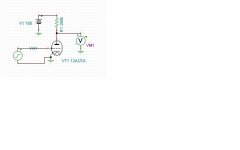
As drawn in your schematic, the 12AU7 is biased through the leakage current of the input coupling cap. Don't have a 10meg, try a 2.2meg at least. 😉
Don't leave the grid 'floating'.
Unfortunately I barely have anything over 50K at the moment, I'm going to order a large assortment of resistors within the next week though. I'll order some 10megs when I do, I figure I'll just stick with the values in the trusty chart/schematic.
I'm still sort of amazed that 10meg can actually do anything, when I think of 10meg, I think of input impediances of devices, which are usually 10meg as to not interfere with the circuit.
The grid of your 12AU7 has to be biased negatively compared to the cathode.
This can be done by grid leak biasing (using electrons trickling out of the grid) using a high value resistor to ground.
Alternatively, you could use the plain vanilla version with a resistor from cathode to ground. You can then decide if you want to have feedback or not (by bypassing the resistor with a cap, so it does not affect the AC signal).
I hope this makes things clearer (even with my convoluted way of explaining).
Best,
Martin
I completely understand the concept of what your saying, but I can't seem to wrap my head around one part. I could understand that the resistor would pull the grid more negative in relation to the cathode if the cathode wasn't already at practically 0V. I would think that the cathode being directly connected to ground VS the grid having a resistor (a high value at that) would still make the cathode more negative.
Or am I missing something? Do you mean that the grid has to be negative, relative to ground, relative to its cathode (how you normally think of Biasing), or do you possibly not mean that it has to be negative at all. I ask this because I thought a resistor in this position would only tie or reference the signal to ground, I can't see how it could make it more negative than the cathode if the cathode is tied directly ground.
Still after typing all of this I am sitting here and wondering about this 10meg on the grid. I completely understand that it should not be floating in general in fact I would've put in a resistor if I had an appropriate one, but I just can't see how a resistor connected to ground can be more negative than ground itself. Unless there's something along the lines of the deficit of electrons on the grid pulls it negative, but even then I don't get it because the grid is going to have ac signals of up to 2V, I can't see how that huge resistor can then shift that entire ac waveform into the negatives.
To clarify one thing, I'm not questioning the legitimacy of what your saying, but rather questioning the reason and how, of what your saying.
Last edited:
Grid leak biasing is not easy to understand if you do not think about where the name is actually coming from:
No matter which way to skin your cat, the grid has to be biased negatively with respect to the cathode.
Having a 10 M resistor from grid to ground would put the grid on the same potential as the cathode if that is also tied to ground. But this is only part of the story.
There are electrons captured by the grid that have to go somewhere. The grid bias resistor is chosen so high that these electrons actually develop a negative voltage on the grid because they cannot flow unrestricted to ground.
Normally (for example with cathode biasing) you would like to avoid having these electrons developing a significant voltage on the grid since it would move your bias point. If you read tube datasheets carefully, you will find that there is a maximum value for the grid leak resistor given for a certain biasing technique (usually higher for cathode bias than for fixed bias - think about it why that is).
For grid leak biasing, it is important that your input cap is not leaky.
In general, your grid always needs a reference to ground (grid resistor). The value is determined by the biasing method. Very high (2-10M) for grid leak, usually in the range of 100k-1M for cathode bias, and 47k-470k for fixed bias - but that really depends on the tube you are using. Because it depends on the amount of electrons "leaking from the grid".
I hope this makes things more clear.
Martin
Grid leak bias has a certain clean sound, but restricts you to using a fraction of the actual bias potential. So say it biases up to -1V (impossible to accurately determine by the way) the input signal it will cope with will be just about 0.2V before distortion starts to climb.
I have used it successfully, and to good effect, in two designs - but both respected the input signal restriction so remained relatively low distortion designs.
I suggest that in this particular design you would be far better off sticking with a resistor for cathode bias.
Shoog
I have used it successfully, and to good effect, in two designs - but both respected the input signal restriction so remained relatively low distortion designs.
I suggest that in this particular design you would be far better off sticking with a resistor for cathode bias.
Shoog
He only has 180V B+. That's not much for a 12AU7.
For regular cathode bias, try something like 50k from grid to ground, 470 ohms from cathode to ground, and change the plate resistor to something like 10K or 20K ohms. I haven't modeled this so it may not be optimum.
For regular cathode bias, try something like 50k from grid to ground, 470 ohms from cathode to ground, and change the plate resistor to something like 10K or 20K ohms. I haven't modeled this so it may not be optimum.
Grid leak biasing is not easy to understand if you do not think about where the name is actually coming from:
No matter which way to skin your cat, the grid has to be biased negatively with respect to the cathode.
Having a 10 M resistor from grid to ground would put the grid on the same potential as the cathode if that is also tied to ground. But this is only part of the story.
There are electrons captured by the grid that have to go somewhere. The grid bias resistor is chosen so high that these electrons actually develop a negative voltage on the grid because they cannot flow unrestricted to ground.
Normally (for example with cathode biasing) you would like to avoid having these electrons developing a significant voltage on the grid since it would move your bias point. If you read tube datasheets carefully, you will find that there is a maximum value for the grid leak resistor given for a certain biasing technique (usually higher for cathode bias than for fixed bias - think about it why that is).
For grid leak biasing, it is important that your input cap is not leaky.
In general, your grid always needs a reference to ground (grid resistor). The value is determined by the biasing method. Very high (2-10M) for grid leak, usually in the range of 100k-1M for cathode bias, and 47k-470k for fixed bias - but that really depends on the tube you are using. Because it depends on the amount of electrons "leaking from the grid".
I hope this makes things more clear.
Martin
Thank you very much for this information. I think I understand how the grid leak bias works now. Thank you for explaining the range of normal values of resistor to use for the different bias methods, that definitely will come in handy as I might end up changing from grid leak to other biasing methods.
Grid leak bias has a certain clean sound, but restricts you to using a fraction of the actual bias potential. So say it biases up to -1V (impossible to accurately determine by the way) the input signal it will cope with will be just about 0.2V before distortion starts to climb.
I have used it successfully, and to good effect, in two designs - but both respected the input signal restriction so remained relatively low distortion designs.
I suggest that in this particular design you would be far better off sticking with a resistor for cathode bias.
Shoog
Can you explain why you'd prefer a cathode bias in this particular setup?
He only has 180V B+. That's not much for a 12AU7.
For regular cathode bias, try something like 50k from grid to ground, 470 ohms from cathode to ground, and change the plate resistor to something like 10K or 20K ohms. I haven't modeled this so it may not be optimum.
The datasheet has charts for configurations all the way down to 90V, so I think I have enough voltage.
As I said to Shoog, I probably won't (but still might) use cathode bias. If I do I'll be sure to try out the configuration you've suggested.
Thank you everyone for your help! 🙂
Last edited:
The datasheet has charts for configurations all the way down to 90V, so I think I have enough voltage.
As I said to Shoog, I probably won't (but still might) use cathode bias. If I do I'll be sure to try out the configuration you've suggested.
Thank you everyone for your help! 🙂
Yeah, but it ain't linear down there....
Yeah, but it ain't linear down there....
It can't be too bad considering the chart/schematic in the datasheet which told me how to setup my gain stage had all the values of resistors for B+'s of 90, 180, or 250, and each were measured with less than 5% distortion (which I realize is not good but I can't see it being even 5% as it is)
It can't be too bad considering the chart/schematic in the datasheet which told me how to setup my gain stage had all the values of resistors for B+'s of 90, 180, or 250, and each were measured with less than 5% distortion (which I realize is not good but I can't see it being even 5% as it is)
Why are you arguing with people who are offering you suggestions?
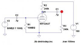
While I'm not sure I can simulate grid leak bias in Tina, I set the internal impedance of the voltage generator to 100M ohms. Distortion is 26% @ 218mV output @ 1kHz. That is horrendously bad. If I have the plate resistor correct at 280k ohms, since your schematic is no longer up here, so I don't know for sure, then you only have 9 volts DC at the plate of the tube.
Simulated the second way with a 100M ohm resistor from grid to ground, distortion is still 15% with only 9 VDC at the plate.
I don't think this is a good design.
Attachments

Why are you arguing with people who are offering you suggestions?
While I'm not sure I can simulate grid leak bias in Tina, I set the internal impedance of the voltage generator to 100M ohms. Distortion is 26% @ 218mV output @ 1kHz. That is horrendously bad. If I have the plate resistor correct at 280k ohms, since your schematic is no longer up here, so I don't know for sure, then you only have 9 volts DC at the plate of the tube.
Simulated the second way with a 100M ohm resistor from grid to ground, distortion is still 15% with only 9 VDC at the plate.
I don't think this is a good design.
That simulation cannot be correct, there is no way I'm getting 26% distortion, not to mention how horribly useless a 218mv output would be.
I decided to force myself to try again to use LTspice IV, and I threw in my little gain stage and I see a 1KHz output swinging about 28V on the output of my gain stage. I'm not sure if its my horrible ltspice skills or what but there is slightly more voltage positive than negative on that output, as well as some other anomoly I see which is the input after the input coupling cap shifts downward AND the output clips on the negative side of the waveform if I remove the input coupling cap......
As you can see we can't completely trust my simulation abilities but they should mean something.
There's no way I only have 9V after my plate resistor (its 240 by the way).
Unfortunately I don't know how to measure distortion in LTspice or I would. (can anyone enlighten me perhaps?)
Sorry the schematic is gone too, I'm doing some work on my website, itll be back in a few days.
I've attached a schematic of the gain stage I'm using and that I simulated in LTspice, the red dot is where I measured the output.
Attachments
Last edited:
Well, like I said, Tina probably isn't good at simulating grid bias, so the results I got are probably not accurate. You can ask others here for advice on LT Spice. It is popular.
Grid leak bias = Leakage current from the grid producing the bias voltage for grid to cathode potential that estabishes the operating point of the tube.
Love your icon. Maxel (UDXL) tape from the late 70s.
Love your icon. Maxel (UDXL) tape from the late 70s.
Grid leak bias = Leakage current from the grid producing the bias voltage for grid to cathode potential that estabishes the operating point of the tube.
Love your icon. Maxel (UDXL) tape from the late 70s.
Thanks. 🙂
Yeah, little bit of a brain burp there... of course, grid LEAK bias...
I assume that the spice model I'm using in Tina isn't up to snuff in that area, that's probably why it doesn't work very well.
Yeah I definitely need to do some more learning about LTspice. Doing simulations of distortion would be really really handy.
None of the simulation software model extreme tube conditions well. Grid leak bias is an extreme condition and relies on grid current - grid current is not modelled at all in most spice models so you can safely chuck out anything SPICE has to say about grid leak bias.
I would not use it because I know that for any reasonable power amp input stage it will produce orders of magnitude more distortion than cathode bias. It is appropriate for only a tiny range of specific applications.
If you don't understand something - please listen to the advice of people who do.
Shoog
None of the simulation software model extreme tube conditions well. Grid leak bias is an extreme condition and relies on grid current - grid current is not modelled at all in most spice models so you can safely chuck out anything SPICE has to say about grid leak bias.
I would not use it because I know that for any reasonable power amp input stage it will produce orders of magnitude more distortion than cathode bias. It is appropriate for only a tiny range of specific applications.
If you don't understand something - please listen to the advice of people who do.
Shoog
OK, then, I now realize that spice can't accurately model grid leak bias.
Thank you for now telling me WHY not to use grid leak bias.
"If you don't understand something - please listen to the advice of people who do."
This sort of thing always gets under my skin. I'm not sure why people that "understand something" get offended so quickly if I fail to say something like "Yes Sir! I'll do that right away your highness!". Its not like I threw out any of your suggestions, I didn't specifically say I'd use them, but I also didn't specifically say I wouldn't use them. There could be many reasons for me not using other people's suggestions, the main reason is that I want to know WHY I should do something, WHY your suggestion is better, HOW it will improve my design, not just, "you should do this because it's obviously better and I'm an expert".
I'm not trying to offend anyone but, it's quite simple, I do these projects to learn, and getting suggestions with no reasoning behind them (not telling me why something is better) doesn't help me learn. All I ask is that you just do a bit of explaining about your suggestions, which shouldn't be a problem, I don't know why it is.
Now back to the cathode bias debate. How much gain do you think I can achieve? My current gain stage is supposed to produce a gain of 16, giving me 20V out. I haven't measured it yet but lets suppose this really is producing exactly that. I haven't mentioned yet but I actually need much more gain, I'm unable to drive this amplifier into clipping from a computer's volume maxed out. The only way I've pushed it into clipping was with my little Low Voltage Line Level Tube Preamp, which can put out 5V of signal on a whim. Do you think that a cathode bias can give me the sort of gain I want?
Last edited:
OK, then, I now realize that spice can't accurately model grid leak bias.
Thank you for now telling me WHY not to use grid leak bias.
"If you don't understand something - please listen to the advice of people who do."
This sort of thing always gets under my skin. I'm not sure why people that "understand something" get offended so quickly if I fail to say something like "Yes Sir! I'll do that right away your highness!". Its not like I threw out any of your suggestions, I didn't specifically say I'd use them, but I also didn't specifically say I wouldn't use them. There could be many reasons for me not using other people's suggestions, the main reason is that I want to know WHY I should do something, WHY your suggestion is better, HOW it will improve my design, not just, "you should do this because it's obviously better and I'm an expert".
I'm not trying to offend anyone but, it's quite simple, I do these projects to learn, and getting suggestions with no reasoning behind them (not telling me why something is better) doesn't help me learn. All I ask is that you just do a bit of explaining about your suggestions, which shouldn't be a problem, I don't know why it is.
Now back to the cathode bias debate. How much gain do you think I can achieve? My current gain stage is supposed to produce a gain of 16, giving me 20V out. I haven't measured it yet but lets suppose this really is producing exactly that. I haven't mentioned yet but I actually need much more gain, I'm unable to drive this amplifier into clipping from a computer's volume maxed out. The only way I've pushed it into clipping was with my little Low Voltage Line Level Tube Preamp, which can put out 5V of signal on a whim. Do you think that a cathode bias can give me the sort of gain I want?
I told you in my first response why Grid Leak bias only allows you to use a tiny proportion of the available gain of an input stage. I told you that it works for a very limited range of applications - input stages not been one of them. Other people told you the reasons.
We all learn for trying but you have had plenty of good advice to avoid making an obvious mistake.
Your going to get a maximum of about 10x voltage amplification with a 12AU7a unless you CCS load the plate when this climbs to about 17x. I would say that either situation would probably be rather low for my taste.
Shoog
Last edited:
I told you in my first response why Grid Leak bias only allows you to use a tiny proportion of the available gain of an input stage. I told you that it works for a very limited range of applications - input stages not been one of them. Other people told you the reasons.
We all learn for trying but you have had plenty of good advice to avoid making an obvious mistake.
Your going to get a maximum of about 10x voltage amplification with a 12AU7a unless you CCS load the plate when this climbs to about 17x. I would say that either situation would probably be rather low for my taste.
Shoog
I'm glad that you were able to get through my last post without having an issue, I had many people mad at me in other places for posts like that, but I said what I had to and now hopefully we can understand each other more clearly.
To be fair, all of those reasons were said, but my main reasons that would give rid leak the boot is gain and distortion.
I do wonder if that 10x is good enough, if I remember correctly the average PC puts out 2V so that would give me 20V after the first gain stage. If I'm thinking correctly I'd have to make a CCS with silicon devices no? I'd prefer not to do that because I wanted this to be tube only (except the rectification). I was already considering using a different driver tube, perhaps I should look into doing that more.
But let me ask you a huge question I've always had. I observed from the start that tubes will cause an audio signal to be inverted. Currently with my single gain stage, and single output stage, the output is the same as the input, not inverted. Can I possibly utilize the second triode in my 17AU7A or is that inverting of the audio signal going to cause a problem, or can I perhaps switch the outputs of my OPT or something. I never really understood if that would be a problem other than the fact that if this amp had an inverted signal going to one speaker, and another had a non-inverted signal, they would cancel out each others sounds which is definitely something I'd like to avoid.
Thanks again for the help, I do appreciate it 🙂
Last edited:
The use of written language without looking into the other person's face, always has the potential for misunderstandings. That's why emoticons are used but they do not help entirely.
I don't think anyone here is telling you what to do or not, those are merely suggestions and you are free to take of all that what you prefer.
Actually, just because I find one design superior to another (even possibly with good arguments) doesn't mean you cannot built the inferior design and be happy with it.
On the other hand, your approach "...the main reason is that I want to know WHY I should do something, WHY your suggestion is better, HOW it will improve my design, not just, "you should do this because it's obviously better and I'm an expert"..." is perfectly valid. That's how we all learn. By trying to understand WHY something works.
My opinion is that if I try to convince you that one design is superior to another, I should also give you the rational behind that. That's at least the theory. In practice this could lead to very long posts and not all of use are willing to spend that time/effort (and that's their own choice - period).
Now back to the your gain stage.
By using a constant current source as load and a cap-bypassed resistor at the cathode, you can achieve maximal gain (almost mu). If you are not afraid of a bit silicon that's easy to implement. A pentode might work as CCS, too if you do not like sand.
You could also use a constant voltage sink in the cathode (a simple LED is a good enough approximation).
The nice think about the CCS is that you can easily change the current through the tube and see what you prefer (if your CCS is variable).
I had so far very good experience with that - and I liked what I heard.
But don't take my word for it - try it out yourself, it's easy.
Martin
PS: I am obviously too slow - my post got a bit redundant
I'm glad that you were able to get through my last post without having an issue, I had many people mad at me in other places for posts like that, but I said what I had to and now hopefully we can understand each other more clearly.
To be fair, all of those reasons were said, but my main reasons that would give rid leak the boot is gain and distortion.
I do wonder if that 10x is good enough, if I remember correctly the average PC puts out 2V so that would give me 20V after the first gain stage. If I'm thinking correctly I'd have to make a CCS with silicon devices no? I'd prefer not to do that because I wanted this to be tube only (except the rectification). I was already considering using a different driver tube, perhaps I should look into doing that more.
But let me ask you a huge question I've always had. I observed from the start that tubes will cause an audio signal to be inverted. Currently with my single gain stage, and single output stage, the output is the same as the input, not inverted. Can I possibly utilize the second triode in my 17AU7A or is that inverting of the audio signal going to cause a problem, or can I perhaps switch the outputs of my OPT or something. I never really understood if that would be a problem other than the fact that if this amp had an inverted signal going to one speaker, and another had a non-inverted signal, they would cancel out each others sounds which is definitely something I'd like to avoid.
You could use it as a Cathode follower after your input stage which would give you the same result.
A CCS would be a silicon beast - which I would have no issue with - but you obviously do.
Consider a higher mu triode - this should work since the sweep tube should represent a fairly easy load. Alternatively consider a nice pentode driver, my goto pentode is the 6AU6 which combines reasonable drive current and good gain.
Shoog
The 6AU6 is probably a good choice.
I am experimenting at the moment with EF80 as driver - just because it's dirt cheap and I have plenty lying around (actually EF805S). it doesn't have the best reputation as an audio tube - but I have fun testing.
A ECC88 with CCS and LED bias might be a good given your low B+.
You can get a gain of around 33.
Martin
- Status
- Not open for further replies.
- Home
- Amplifiers
- Tubes / Valves
- 6CU6 Sweep Tube Monoblock Power Amp Build Log