Just what we need, another 6CA7/EL34 push pull amp. I apologize in advance.
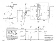
Here is my version of an ultra-linear 6CA7 push-pull amp. The input stage is a classic mu follower with the output taken from the lower triode to allow for quasi direct coupling to the phase inverter. Taking the output from the lower triode may make this more recognized as a common-cathode stage with a CCS load.
I had posted this unfinished design in another thread with questions and the responses were helpful. I originally built this with an under-sized PT so I could not bias the 6CA7s properly. This was built with the proper size power xfmr.
The first stage is direct coupled to the cathodyne phase inverter via a step network/voltage divider using a 220nF cap across the top resistor, for a -3dB point of 2.2Hz.
The RC compensation network prior to the voltage divider controls ringing at the output. Feedback to the input stage restores symmetry to a 100Hz test square wave.
The cathodyne phase inverter directly drives the 6CA7 cathode-biased, class A push-pull outout stage. The output of the cathodyne is 120V P-P/42V RMS right before clipping. Plenty to drive the 6CA7s. The 6CA7s are biased at 56mA, about 21 watts dissipation.
The 6CA7 output stage clips well before the driver or the phase inverter. I measured 22.5W RMS across an 8 ohm dummy load at the onset of clipping with a 1kHz sine wave. Input sensitivity is 1V RMS. Hum and noise at the output is about 1mV. Dead quiet.
The amp sounds very good. Excellent bass response. Very well-balanced mids and highs. Crystal clear sounding to me. I have no way to perform harmonic distortion measurements at this time. I have read that the Right Mark Audio Analyzer will do those measurements, so as soon as I learn how to use it I will post the results.
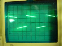
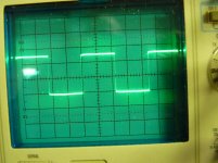
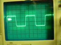
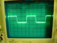
I have attached a few square wave photos. These are taken at 2.83V across an 8 ohm dummy load. The first is 100Hz without feedback. The second is 100Hz with feedback. The feedback clearly squares up the wave. The third is 2kHz. The fourth shows the actual square wave output of my function generator at 2kHz. Pretty bad, I know. I either need to repair or replace that unit.
edit : The specs for the power supply choke shown on the schematic are wrong. The choke is rated for 250mA.
edit: I just noticed that the diodes are shown backwards. They should be connected cathode to the 5AR4 plate. They are correct in my build. My drawing program has been doing some funky things lately, like when I modify a document created on my Linux machine, and then work on it on my Windows 7 machine. Things seem to get changed or flipped like in this case.
Here is my version of an ultra-linear 6CA7 push-pull amp. The input stage is a classic mu follower with the output taken from the lower triode to allow for quasi direct coupling to the phase inverter. Taking the output from the lower triode may make this more recognized as a common-cathode stage with a CCS load.
I had posted this unfinished design in another thread with questions and the responses were helpful. I originally built this with an under-sized PT so I could not bias the 6CA7s properly. This was built with the proper size power xfmr.
The first stage is direct coupled to the cathodyne phase inverter via a step network/voltage divider using a 220nF cap across the top resistor, for a -3dB point of 2.2Hz.
The RC compensation network prior to the voltage divider controls ringing at the output. Feedback to the input stage restores symmetry to a 100Hz test square wave.
The cathodyne phase inverter directly drives the 6CA7 cathode-biased, class A push-pull outout stage. The output of the cathodyne is 120V P-P/42V RMS right before clipping. Plenty to drive the 6CA7s. The 6CA7s are biased at 56mA, about 21 watts dissipation.
The 6CA7 output stage clips well before the driver or the phase inverter. I measured 22.5W RMS across an 8 ohm dummy load at the onset of clipping with a 1kHz sine wave. Input sensitivity is 1V RMS. Hum and noise at the output is about 1mV. Dead quiet.
The amp sounds very good. Excellent bass response. Very well-balanced mids and highs. Crystal clear sounding to me. I have no way to perform harmonic distortion measurements at this time. I have read that the Right Mark Audio Analyzer will do those measurements, so as soon as I learn how to use it I will post the results.
I have attached a few square wave photos. These are taken at 2.83V across an 8 ohm dummy load. The first is 100Hz without feedback. The second is 100Hz with feedback. The feedback clearly squares up the wave. The third is 2kHz. The fourth shows the actual square wave output of my function generator at 2kHz. Pretty bad, I know. I either need to repair or replace that unit.
edit : The specs for the power supply choke shown on the schematic are wrong. The choke is rated for 250mA.
edit: I just noticed that the diodes are shown backwards. They should be connected cathode to the 5AR4 plate. They are correct in my build. My drawing program has been doing some funky things lately, like when I modify a document created on my Linux machine, and then work on it on my Windows 7 machine. Things seem to get changed or flipped like in this case.
Attachments
Last edited:

audiohead: "Hey, what is story with cathode bypass cap of the mu follower?"
I was thinking the same thing. The cap AC grounded the cathode. . . it would defeat the NFB . . .
Hey, what is story with cathode bypass cap of the mu follower?
Looks like he forgot to draw one more resistor in series.
hi,
i have an old baldwin 40 PTX, i dont know the secondary resistence of it, how can i mearesure it?
i will be following this thread for sure.
Just measure the resistance with an ohmmeter from the center tap to both sides of the secondary.
Looks like he forgot to draw one more resistor in series.
Nothing forgotten. The very minimal feedback clearly restores the low frequency component. Nothing more needed or intended.
Feedback operates below about 8Hz, so will do little but shift LF phase up to about 80Hz. I can't see the point in this, apart from perhaps making up for the lack of any LF rolloff at the input of the amp.scitizen17 said:The very minimal feedback clearly restores the low frequency component.
Nothing forgotten. The very minimal feedback clearly restores the low frequency component. Nothing more needed or intended.
Then you don't need the compensation network or the cap across the feedback resistor. All of those components are there in a normal design to ensure closed-loop HF stability.
You might add some reactance to your dummy load (or use a speaker) to see what happens to those square waves.
What are the diodes in series with the tube rectifier for?
I'm running the 5AR4 pretty close to max here. It has been recommended by several folks here to add the diodes for prevention of arcing in the rectifier at turn-on. This is a common mod over on the Dynaco forum.
Looks like he forgot to draw one more resistor in series.
Can I lift the ground end of the RC cathode circuit, insert say a 100 ohm resistor to ground, and then apply the feedback at the junction of the RC circuit and the 100 ohm resistor?
The grid voltage of cathodyne ( 65 V ) is not optimum. Should be some 80...85 V when Ub = 300 V.
When I calculated the load line for the 6922EH, 70V across the plate and cathode resistors indicated a point for equal voltage swing across the inverter. If I change the grid voltage wouldn't I also have to change the plate and cathode resistor value?
Yes. You would of course have to change the value of the feedback resistor so you get whatever feedback you thought you had before.
Can you recommend a starting point for the value? I don't believe I need a large amount of feedback. The amp sounds great just like it is. Maybe no feedback at all would be better?
- Status
- This old topic is closed. If you want to reopen this topic, contact a moderator using the "Report Post" button.
- Home
- Amplifiers
- Tubes / Valves
- 6CA7 UL Push Pull Amp Design