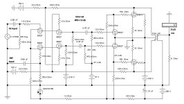
Anybody know if this has been done before? Basically an pentode LTP driving a pair of 6C33's. Trick is to allow negative feedback to the screens of the LPT from the plates of the 6C33. On simulation has a dramatic effect on THD and there seems to be an optimal value for R17. Would this work and am I within the specs for the 6EJ7's. Its a little difficult to get enough output swing to drive the triodes. Any comment would be helpful.
Attachments
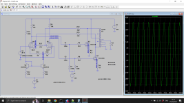
If its not torn up in pieces on diyaudio, I may build a prototype to see. Maybe use a hammond 1650M as OPT. The primary impedance seems to need to be low. I expect it will have high damping factor too. There's lots of 6C33 around and given the heater current they should put on a good display. I quite like the 6ej7 with its frame plate you can see through to the cathode.

I have seen it called driver UL (using the UL taps instead). It is also a form of "tube emulation" where the output tube is controlled so as to copy the internal triode in the driver tube. If the output tube (feedback) does not conform to the driver Mu factor, the the driver changes its plate current drive to make it do so. I've mentioned the idea a number of times over the years. Jan E. Veiset did an Amp using this, many years back, with a bunch of other local and global Fdbks along side. Was too ambitious and oscillated due to phase shift at the UL taps. The quality of the final output does depend on the quality of the internal driver triode. A power Beam Pentode output can also be linearized (into a quality triode) this way too. With low output Z. Good for Sweep tubes with their obnoxious square law gm.
The idea can work, but it's tricky to get the AC and DC levels at the driver screens where you want them simultaneously. You may want a pull-down resistor or two in the Fdbk attenuator to get DC screen V where it is driver tube friendly (and a more linear triode).
The 6EJ7 may be a little undersized here. Could try gyrator loads for it, or use the slightly bigger (3.1 Watt) 6JC6A tube. (but same 0.3 Amp Htr current, so no extra plate current) Some Westinghouse (made in Japan) 6JC6A tubes I came across had beautiful internal triode curves. For more current though, step up to a 12HL7 frame grid pentode driver. Good for up to 50 mA max DC. Curve tracer selected 12HL7 tubes can have an internal triode that would make a 300B weep. 6AH9 has the 12HL7 pentode inside plus a mu 20 2W triode too. 12HL7 triode curves:
The idea -could- be applied to SE too, but for correct phasing it still needs a splitter and diffl. driver to do the crossed Fdbk, so not so attractive.
Last edited:
What do you mean by "pretty fragile"? I've been using them to drive a pair of KT120 mono amps and they are great sounding tubes.Well worth pursuing. There may be a better choice in terms of pentodes - the 6EJ7 is pretty fragile.
Other types to consider:
6J9P (Russian)
D3A
E180F
12GN7 (Video pentode)
6BQ5
The 6EJ7 does have an impressive (for it's size) 25 mA DC cathode current limit. But looking in the GE Handbook, I see the 6EJ7 running at 10 mA and the 6JC6A running at 14 mA. It's just the old saying "a skosh more". More seriously though, one should look at the triode mode curves for the selected driver. I don't recall seeing the 6EJ7 triode curves, they may be fine. I do know the Westinghouse (made in Japan) 6JC6A triode curves, and they are impressive. The USA 6JC6A triode curves are N.G. junk.
The Sylvania 12HL7 triode curves can be superb. Watch out for RCA 12HL7 tubes with smaller guts. Something else inside, junk.
The Sylvania 12HL7 triode curves can be superb. Watch out for RCA 12HL7 tubes with smaller guts. Something else inside, junk.
Last edited:
The polarities of V2, V5 are correct?
Yeah, I think -negative- V would normally be expected there, to run the CCS supplies. Spice probably doesn't care.
4P1L (7.5 Watt, 55 mA max DC pentode) has great triode curves (like zero 2nd Harmonic) for the driver pentode. But direcly heated. (1st pic below)
For something with just a little 2nd H in triode, there is 6197 7.5 Watt, 50 mA max DC. (2nd pic below) 6197 excellent pentode curves, 3rd pic below:
All cheap tubes mentioned so far.
Probably many suitable driver tubes around, but some curve checking needed.
Last edited:
The 6EJ7 triode curves are super linear and yeah, I've used those 6JC6A tubes in triode, they also sound very good.More seriously though, one should look at the triode mode curves for the selected driver. I don't recall seeing the 6EJ7 triode curves, they may be fine. I do know the Westinghouse (made in Japan) 6JC6A triode curves, and they are impressive.
Oh, I just noticed that the normally "negative" supplies, shown on the schematic as positive ones, have a - sign on the assigned voltages. So all is normal, just confusing.
The low mu 6C33 (mu 2.7 ? ) could be replaced with a 6528 regulator triode (mu 9 ) for better grid sensitivity, and an Octal socket.

The low mu 6C33 (mu 2.7 ? ) could be replaced with a 6528 regulator triode (mu 9 ) for better grid sensitivity, and an Octal socket.
Last edited:
Great idea!
Try it.
Local negative feedback has the advantage that it does not involve the output transformers phase and frequency response character.
Yes, I admit, the output transformer can have its' own harmonic distortion and Intermodulation distortion; In that case try and use the best performing transformer you can find.
By the way, global negative feedback taken from the output transformer secondary, does not fix transformer saturation, it actually makes it worse.
Caution:
3C33 with 4.7 Ohm sense resistor in the cathode, and only a Common, single fixed bias voltage going to both tubes may not be the best way to prevent:
Unbalanced plate currents in the output transformer primary. Output transformers Hate that.
One or more 3C33 going into Thermal Run-Away.
I am a fan of Individual Self Bias resistors.
Next choice, I am a fan of extremely well matched tubes, plus a Common single self bias resistor.
Give those tubes a chance.
With Self bias, you lose a little output power . . . that is until the fixed bias version of the amplifier blows up!
Then which Bias Type has more power?
I see lots of posts in Tubes/Valves that list problems both with fixed bias and with fixed adjustable bias for 3C33 tubes (even if the fixed bias is individually set for each tube).
Just my opinions.
Last edited:
Oops, in post #5, I messed up the operating description. The screen feedbacks will cause the driver plates to adjust -voltage- to get mu times the input delta V (at the grid1s) to occur on the screens (from the output tube plates). Just like a triode, delta V screen over delta Vg1 stays a constant, mu. The grid 1 inputs do set a driver current partition in the differential stage, for 1st order output drive, but the screen grid feedbacks will fine tune that ratio to get the V ratio from input signal to final output V signal in the ratio of mu. When mu is satisfied, the plate current then stays constant, otherwise it changes the current ratio until mu is satisfied. Using gyrator loads for the driver plates makes for very high gain in the control loop. Driver Ri constrains the loop gain possible.
With the gyrator driver loads, the current in the two driver tubes will stay near equally partitioned, as the grid1 input signals and the screen feedback signals swing in opposite directions by mu ratio to keep the driver tube currents near steady. The driver plate voltages will however be swinging to whatever voltages are required to get the output tube to behave properly for mu enforcement. Made possible by the high Z gyrator loads. Essentially a tube Op. Amp controller. Adjusting the final output until the feedback nulls the input (with a mu factor N Fdbk attenuator to get mu gain plus any resistive attenuation factor). The driver mu does change slightly with input voltage here, so you get a triode gain result.
Lowering the gyrator Z (to some resistor instead) will give you the same result as a loaded triode, with increased 2nd harmonic.
Last edited:
Which would show up as increased 3rd harmonic in this P-P case.
Anyway, this is an excellent type circuit to get high $$ results from low cost tubes. Using a practical OT and B+. With a high damping factor output.
You could even put Mosfets in for the output tubes and still get super triode results. Beam triodes (6HZ5), Sweep tubes, parallel tube banks ..... bring them on !!
Last edited:
Nothing to do with how they sound, a lot more to do with their plate dissipation and voltage withstand. Never said they were not good sounding. The 6C33 is a low mu triode and presumably requires larger voltage swings to drive effectively than a KT120. Don't know for sure as my experience is limited to the 6C33.What do you mean by "pretty fragile"? I've been using them to drive a pair of KT120 mono amps and they are great sounding tubes.
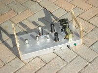
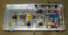
Here is something similar I built as an experimental project 15-20 yrs ago.
Its been described here on DIY several times in the past.
I had three objectives in mind. One of those was a PP 6V6s circuit in Class AB2, G1s driven by PP CFs.
Max output on a lab supply was 26 watts. Another objective, output max & regulation while powered
by a limited PS, such as we might see in the case of a guitar amp of the 50s & 60s. So 19 watts.
The last was a form of internal NFB as I'd seen on a visit to Bill Perkins (PEARL) notes while on a business
trip to Calgary. In Bills case the NFB was from a tertiary winding on the OPT back to screens on PP drivers.
Some years later I got back on all that & figured the NFB could go to the top grids in a
PP Cascode front end instead of screens.
The Mule is not built for beauty, strictly experimental as are all my projects for the past 25 yrs.
Attachments
That's a very interesting design. Same functionality, but no screen currents to contend with using a cascode design.
I should mention that Jan Veiset's design used a special proportional scaling of the N feedback voltages going to the driver screens (versus driver plate voltages), so that they would intercept a near constant fraction of the plate currents. This made the screens look like a constant resistance. Otherwise some followers driving the screen grids might be called for to keep the resistive feedback attenuation constant. A proportional ratio between driver screen V and driver plate V. This may be what Baudouin0 is finding with variation of R17, giving a lowest distortion setting. Would be interesting to put the driver screen V and driver plate V on a dual trace scope (or in the simulation) to see if they follow some proportional ratio for Baudouin0's design. ( But I wonder if the simulation's tube model has accurate screen current modeling. )
I should mention that Jan Veiset's design used a special proportional scaling of the N feedback voltages going to the driver screens (versus driver plate voltages), so that they would intercept a near constant fraction of the plate currents. This made the screens look like a constant resistance. Otherwise some followers driving the screen grids might be called for to keep the resistive feedback attenuation constant. A proportional ratio between driver screen V and driver plate V. This may be what Baudouin0 is finding with variation of R17, giving a lowest distortion setting. Would be interesting to put the driver screen V and driver plate V on a dual trace scope (or in the simulation) to see if they follow some proportional ratio for Baudouin0's design. ( But I wonder if the simulation's tube model has accurate screen current modeling. )
Last edited:
This whole triode emulation/driver screen feedback scheme brings up another interesting scheme, Active Ultra-Linear. AUL
Where a separate diffl. amp monitors the input(s) to the output stage, and controls the output tube's screen V to get an accurate amplified output from the plate(s). Compares input signal to a scaled output signal, and adjusts the output tube screen V to get a match. Similar kind of function.
Can use the same diffl. stage to control both output tube screens for P-P.
The scheme can be used for SE outputs too. Lowers output Z greatly too.
Not a triode emulation particularly, but a linearity enhancer.
It can easily be turned into a triode emulation by bringing the monitored/attenuated plate outputs back to the controller diffl. stage screen grids. (instead of resistive summing with input V at it's grid 1's)
Takes two extra pentodes for AUL, a dual pentode 6BN11 could handle it possibly. Use some Mosfet followers for operating the output tube screens.
Last edited:
- Home
- Amplifiers
- Tubes / Valves
- 6C33CB PP amp with ultra linear