I just had to start with this quote... IT DOES WORK! and it works pretty well indeed using 'em old trusty ears and good music.
You will have to accept facts. If the component values are as in your schematic, even with NFB returned to V2 cathode, it will be a disaster. No matter what your ears may say.
Check the voltages at V3 cathode and anode, you will probably have something like 10-20V over the tube.
If it sound and measures OK your schematic is faulty!
Can not find A+, B+ and BIAS in the schematic?
revintage said:
You will have to accept facts. If the component values are as in your schematic, even with NFB returned to V2 cathode, it will be a disaster. No matter what your ears may say.
Check the voltages at V3 cathode and anode, you will probably have something like 10-20V over the tube.
If it sound and measures OK your schematic is faulty!
Can not find A+, B+ and BIAS in the schematic?
Tja... some people tell me my ears are broken... so its my fault hey?
A+ = ~290V
B+ = ~360V
BIAS = ~180V
So... I will try your schematic and hear how it sounds...
Re: Re: Hum on SE...
Right.....
In comparison to what you have already done to to this is a doddle....
We need to 'float' the heaters to around 40V above ground potential to remove the 'diode-action' between the heater and the cathode. In a Perfect-world, and perfect valve we would not need to do this, but you and I live in the Real-World!
Right, to do it, try this....
Take a 150K resistor and connect it to the 200V +B rail, that supplies the '33 anode-volts. Connect other end to the heater-supply at the mains Tx, either connection will do. Remove any connections you have made from the heater circuit to ground.
Now, take a 47K and connect it to the same heater connection as the 150K is attached to, and connect the other end to ground.
Across the 47K from heater con. to ground, place a 0.22uF cap with a 200V or higher volts rating.
--Job done....
IF you are suffering heater-induced hum from the 'diode-action' of the heater and the cathode, this will cure it......
😀
GlidingDutchman said:
Okay... can you guide me please. I only know the basics.
Right.....
In comparison to what you have already done to to this is a doddle....
We need to 'float' the heaters to around 40V above ground potential to remove the 'diode-action' between the heater and the cathode. In a Perfect-world, and perfect valve we would not need to do this, but you and I live in the Real-World!
Right, to do it, try this....
Take a 150K resistor and connect it to the 200V +B rail, that supplies the '33 anode-volts. Connect other end to the heater-supply at the mains Tx, either connection will do. Remove any connections you have made from the heater circuit to ground.
Now, take a 47K and connect it to the same heater connection as the 150K is attached to, and connect the other end to ground.
Across the 47K from heater con. to ground, place a 0.22uF cap with a 200V or higher volts rating.
--Job done....
IF you are suffering heater-induced hum from the 'diode-action' of the heater and the cathode, this will cure it......
😀
revintage said:About the lousy 5814/ECC82, I would say it is not good enough to drive the 6C33C. 5687 or 12B4 would be the way to go. Or why not a trioded 6E5P.
Or try a tasty E182CC.
Just my two cents but I would think a 5687/E182CC common cathode into a triode strapped EL84 common cathode into the 6C33C would seem to be a really nice circuit. You could direct couple the first two stages and the cap couple the output stage. Just a thought. I really don't care for 12XX7s.
About the lousy 5814/ECC82, I would say it is not good enough to drive the 6C33C.
I hope you are referring to sound quality or distortion. From a current and output impedance aspect, the ECC82 could drive a 6c33c with ease. 6c33c is not that hard to drive
Just my two cents but I would think a 5687/E182CC common cathode into a triode strapped EL84 common cathode into the 6C33C would seem to be a really nice circuit.
El84 would be overkill as a driver.
6c33c takes a fair amount of voltage swing, but other than that it's fairly easy to drive. Grid-current draw and input capacitance aren't that demanding. It has high inter electrode capacitance, but the gain is low (usually around 2), so input capacitance isn't bad. I've found that they do start to draw some grid current Vgk reaches 0V, but it's only like 1mA at most.
Guys... mmm I dont know anymore.
I get totally bowled over by all these negative comments that wants to make me drop the project before I really have started...
Yes, I am a newbie with tubes so be merciful please.
Think I should rephrase:
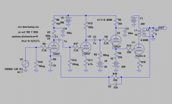
I have a set of 6C33C tubes a couple of odd small signal tubes, a set of Hammond 1640SE trannies and a good mains transfo. What amp can I build with these parts?
I get totally bowled over by all these negative comments that wants to make me drop the project before I really have started...
Yes, I am a newbie with tubes so be merciful please.
Think I should rephrase:
I have a set of 6C33C tubes a couple of odd small signal tubes, a set of Hammond 1640SE trannies and a good mains transfo. What amp can I build with these parts?
I hope you are referring to sound quality or distortion. From a current and output impedance aspect, the ECC82 could drive a 6c33c with ease. 6c33c is not that hard to drive
Off course it is the linearity and sound. No use for current and right impedance if it sounds crappy. As CF it is OK though.
GD,
It is not negative comments, it is as you asked for: "ideas on refinement",😀. I posted a first schematic with your tubes involved earlier. I am also working on another with a DC-coupled 5814 CF into the 6C33C.
So cheer up, we are all trying to help you to get a working amp out of your existing tubes! With some tricks it should be possible to build it without overall NFB.
revintage said:
GD,
It is not negative comments, it is as you asked for: "ideas on refinement",😀. I posted a first schematic with your tubes involved earlier. I am also working on another with a DC-coupled 5814 CF into the 6C33C.
So cheer up, we are all trying to help you to get a working amp out of your existing tubes! With some tricks it should be possible to build it without overall NFB.
Thank you. I get a bit negative because it is frustrating when I dont know "what and how". I think I need to get myself a book like "Morgan Jones Valve Amplifiers".
I guess when I finish the amp I would like it to be something like the Almarro A318B but I dont want to use ultra rare small signal tubes so that is why I am biased towards the common tubes like the 12AX7. I like the good 12AX7 tubes and use them in my E.A.R. 834P phono amplifier. You see, tubes are a rarity here in South Africa so I must use whats available. Electronic parts are ultra rare here in my small town 350 kms from the city Johannesburg.
I get totally bowled over by all these negative comments that wants to make me drop the project before I really have started... Yes, I am a newbie with tubes so be merciful please.
Don't be discouraged. We are just trying to help. You seem skilled for a newbie. People on these forums always give criticism when people post their schematics, don't take it personally. Your end result will probably be a very good sounding amplifier if you stick with it.
The schematic Revintage posted in #12 looks pretty solid. If he finishes a direct coupled version, I'm sure it will be good.
Direct-coupling to a CF driver is desirable (but not mandatory) for the 6c33c when used in fixed bias class-A because the tube has a tenancy to drift. Keeping a low DCR in the grid circuit seems to help stabilize some.
With some tricks it should be possible to build it without overall NFB.
You may want to consider keeping it. Or at least make it switchable. 6c33c amps tend to give inconsistent gain and distortion from tube to tube and they are difficult to match. Getting good balance (sonically and amplitude) between channels can be difficult without it. I find that generally 6dB of global feedback will significantly increase consistency without causing any detectable sonic deficiencies. It actually helps the amp sound less muddy when the music becomes "busy".
I've attempted several local feedback and distortion cancellation schemes for 6c33c SE's . Most local feedback schemes throw PSRR in the toilet and leave the amp as un-predictable as open loop. Distortion cancellation mechanisms have to be adjusted any time one of the tubes are changed. And it is difficult to do distortion cancellation schemes that don't alter gain as a side-effect. The end result for me, was a headache, but perhaps you will have better luck if your attempting one of these approaches.
Never give up!!
Yes, This is the scheme I would use--In fact with a few differences--I did,--more or less!
--Worked out really nicely, and even sounded pretty good with my home-wound output transformers....
Don't give up, This scheme from revintage is pretty straight-forward and a great starting-point, but by all means persue your existing scheme and see how you get on.....
(With this scheme, you'll notice the rather odd Minus 84V supply to the CF driver grid. This voltage sets the bias-point for the '33, via the CF driver. Make it adjustable from say, -70V to -100V and you can trim the bias to exactly what you need....😀
revintage said:Do not look upon this as a ready-made solution, more like an idea. It will although be an acceptable starting point. You will probably get at least 10W under 1% THD.
Yes, This is the scheme I would use--In fact with a few differences--I did,--more or less!
--Worked out really nicely, and even sounded pretty good with my home-wound output transformers....
Don't give up, This scheme from revintage is pretty straight-forward and a great starting-point, but by all means persue your existing scheme and see how you get on.....
(With this scheme, you'll notice the rather odd Minus 84V supply to the CF driver grid. This voltage sets the bias-point for the '33, via the CF driver. Make it adjustable from say, -70V to -100V and you can trim the bias to exactly what you need....😀
(With this scheme, you'll notice the rather odd Minus 84V supply to the CF driver grid. This voltage sets the bias-point for the '33, via the CF driver. Make it adjustable from say, -70V to -100V and you can trim the bias to exactly what you need
Hi Alastair,
What´s odd in simming a circuit with max allowable current through the OPT?
It is so obvious one must make the bias adjustable, so why bother to comment it😉 ! Gliding Dutchman seems to be fully aware of these things.
Odd value...Explanation for OP
Earlier in this thread, The OP was unsure of how to rig up a potential divider from HT to deck to elevate the heaters, as an aid to reduce hum--He admits himself he is a newcomer to tubes....
It AINT Obvious to Everybody,--- just Why there would be what appears at first look an Odd Voltage of -84V supply at this point....
-Not Everybody is a seasoned 'Vintage-Veteran'--🙄
It was NOT in any way a criticism of the scheme or yourself, Mearly an Explanation to someone who may have been unsure...Nothing More...
--In Life, I have learned, Never Take ANYTHING for granted....
Guys!!
Sorry for the late reply...
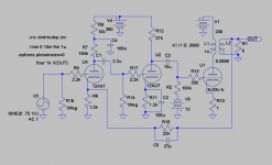
Any ideas on the 6H30Pi tubes as driver tubes? I must admit that these tubes (6H30Pi) has been used in the original prototype amp where I got the parts from.
I popped in the only set of 6H30Pi I have and VOILA!! Sounds much better, more drive, incredible bass!!
Also in the second (driver stage) I placed a resistor between the first "plate" and second "grid" to prevent startup sparking (cathode stripping?).
Elevated the filament supply as per instruction.
Placed 10nF 600V cap on wiper of Bias adj.
Made each output PSU separate with a >> ac-rectifier-cap-coil-cap.
I still have an issue with the 1st stage - too much gain! How can I trim the gain so that it just acts as a buffer stage? Or !! Can I employ the "unused" dual triode as a CCS and/or B+ supply regulator (or something like that) for the 6H30Pi tubes? Maybe get another 6H30Pi for the application.
Otherwise I am enjoying the amps sound.
Sorry for the late reply...
Any ideas on the 6H30Pi tubes as driver tubes? I must admit that these tubes (6H30Pi) has been used in the original prototype amp where I got the parts from.
I popped in the only set of 6H30Pi I have and VOILA!! Sounds much better, more drive, incredible bass!!
Also in the second (driver stage) I placed a resistor between the first "plate" and second "grid" to prevent startup sparking (cathode stripping?).
Elevated the filament supply as per instruction.
Placed 10nF 600V cap on wiper of Bias adj.
Made each output PSU separate with a >> ac-rectifier-cap-coil-cap.
I still have an issue with the 1st stage - too much gain! How can I trim the gain so that it just acts as a buffer stage? Or !! Can I employ the "unused" dual triode as a CCS and/or B+ supply regulator (or something like that) for the 6H30Pi tubes? Maybe get another 6H30Pi for the application.
Otherwise I am enjoying the amps sound.
6H30pi, 6922, ECC88 types should work reasonably as driver for the 6C33, so long as you dont want to 'push' the '33 too hard.
How is it configured? CF or CC
They are designed for moderate voltage use, --which is fine for your 200 odd volts +B
Schematic would be nice....!😀
How is it configured? CF or CC
They are designed for moderate voltage use, --which is fine for your 200 odd volts +B
Schematic would be nice....!😀
Alastair E said:6H30pi, 6922, ECC88 types should work reasonably as driver for the 6C33, so long as you dont want to 'push' the '33 too hard.
How is it configured? CF or CC
They are designed for moderate voltage use, --which is fine for your 200 odd volts +B
Schematic would be nice....!😀
Same as the first schematic. I just popped in the 6H30Pi tubes and had to rewire the heater supply for 6.3v.
The amp seems to be working best with the first stage omitted.
- Status
- Not open for further replies.
- Home
- Amplifiers
- Tubes / Valves
- 6C33C SE Amp - Ideas on refinement?