...more
Hi Frank ,
It's not just that . The heat from the filament seems to be conducted through to the pins . Running the 6C33 hot just makes matters worse
cheers 🙂
316a
fdegrove said:Hi,
Maybe I'm wrong but I thought the problem was caused by the heater current/pins interface?
Cheers,😉
Hi Frank ,
It's not just that . The heat from the filament seems to be conducted through to the pins . Running the 6C33 hot just makes matters worse
cheers 🙂
316a
I'm pretty sure Frank is right.
The filament is 42W; a great deal of heat is passed to these very thin pins, which are much thinner than those of an octal tube. Considering the huge filament current - 6.3 amps - these pins are drastically underengineered in my view. The result is that the tube filament pins oxidise over time, and eventually the resulting resistance cuts back filament voltage. With emission dropping, at high plate dissipation the tube ages since the cathode is now overstressed.
Since there are two filaments and effectively two triodes in parallel, this process does not happen in step between sections, and as one degrades, the other attempts to take up the slack. The imbalance causes more ageing, and the whole thing falls over fairly rapidly.
The use of two sections reflects the original design use for power supply avionics on a MIG fighter. Dual sections is actually more reliable in the short term because aircraft avionics are regularly replaced in service. But for long term audio use, the concept works against reliability as the tube ages.
Cheers,
Hugh
AKSA said:The filament is 42W; a great deal of heat is passed to these very thin pins, which are much thinner than those of an octal tube. Considering the huge filament current - 6.3 amps - these pins are drastically underengineered in my view.
Hi,
current thru 6C33 filaments pins is ca 3A.
Regards
The filament is 42W; a great deal of heat is passed to these very thin pins, which are much thinner than those of an octal tube. Considering the huge filament current - 6.3 amps - these pins are drastically underengineered in my view. The result is that the tube filament pins oxidise over time, and eventually the resulting resistance cuts back filament voltage. With emission dropping, at high plate dissipation the tube ages since the cathode is now overstressed.
That is you own opinion but as I wrote there seems to be no problem if the total dissipation of the tube is kept below 2/3 of max, this seems to be well known among professional users of the tube.
I have as I wrote used the same tubes without moving or removing them for more then 4 years without any problems what so ever, I have also heard all horror stories about oxidising pins and increasing resistance in the sockets but when I measured the voltage drop over the socket connectors it was a few mV which is not a problem.
I think the total dissipation is the cause of the problem as the heater pins heats up as well as all other parts if dissipation is high, if so the solution is as reported to keep dissipation under control.
BTW , I dont think the pins are underengineered for 3A current, there are many professional connectors available with similar pin area with similar or even higher current rating, one simple example are D-sub connectors with solid pins that are rated for up to 5A with much less contact pressure.
Regards Hans
I just can’t help messing, so removing the tubes every few months to clean the contacts really wouldn’t bother me, that's if its even necessary anyway.
Wouldn’t mind having a closer look at the construction of those specially made 6C33 sockets by graaf though, would also be very interesting to find out how they run the tubes in the GM 20 OTL amp.
I think also Graaf may have thought it necessary to make there own sockets to completely eliminate any possible chance of the pins carbonizing just to assure the customer of how reliable there amps are, as would any discerning audio company. So I feel this shouldn’t concern us as we're all DIYers here IMO.
Hesky
To Audiofanatic
Hi there,
Are you saying you have both the schematics and the amplifier??
Could you email me a copy of the schematics? If possible, I wish you can share your project with us by posting some pictures here.
Is this fine with you?😀 😀 😀
Thanks,
Lhchen
Hi there,
Are you saying you have both the schematics and the amplifier??
Could you email me a copy of the schematics? If possible, I wish you can share your project with us by posting some pictures here.
Is this fine with you?😀 😀 😀
Thanks,
Lhchen
Re: To Audiofanatic
Hi contaxchen,
Unfortunately, the schematic is not in my position anymore.
BTW it was a copy of a reversed eng. KORA SB-100 PP 6C33-C amp.
By memory, it uses one SOVTEK 6922 No other 6922 my be used! In differential mode, two EL84 drivers and a complicated construction of the two 6C33-C tubes in PP configuration.
I've listen to the amp for a few weeks and after a month, I desided that I will not make a PP 6C33-C amp but a 300B SE amp, cause the 300B is more my taste than any other tube 😉
So I hope you will not hold it against me, but I don't have the schematic anymore and if I can get hold of it agiain, it's not my IP and therefore I may not publish it on this forum or send it to someone else. I appologize for this.
Best regards,
Audiofanatic 🙄
contaxchen said:Hi there,
Are you saying you have both the schematics and the amplifier??
Could you email me a copy of the schematics? If possible, I wish you can share your project with us by posting some pictures here.
Is this fine with you?😀 😀 😀
Thanks,
Lhchen
Hi contaxchen,
Unfortunately, the schematic is not in my position anymore.
BTW it was a copy of a reversed eng. KORA SB-100 PP 6C33-C amp.
By memory, it uses one SOVTEK 6922 No other 6922 my be used! In differential mode, two EL84 drivers and a complicated construction of the two 6C33-C tubes in PP configuration.
I've listen to the amp for a few weeks and after a month, I desided that I will not make a PP 6C33-C amp but a 300B SE amp, cause the 300B is more my taste than any other tube 😉
So I hope you will not hold it against me, but I don't have the schematic anymore and if I can get hold of it agiain, it's not my IP and therefore I may not publish it on this forum or send it to someone else. I appologize for this.
Best regards,
Audiofanatic 🙄
Hi again,
I have found out another website about 6c33c
http://www.jogis-roehrenbude.de/Leserbriefe/Klaus-PP/Push-Pull.htm
This project looks fine, but I am looking for the best.
😀
Lhchen
I have found out another website about 6c33c
http://www.jogis-roehrenbude.de/Leserbriefe/Klaus-PP/Push-Pull.htm
This project looks fine, but I am looking for the best.
😀
Lhchen
contaxchen said:Hi again,
I have found out another website about 6c33c
http://www.jogis-roehrenbude.de/Leserbriefe/Klaus-PP/Push-Pull.htm
This project looks fine, but I am looking for the best.
😀
Lhchen
There is a schematic of sorts for the Graaf GM20 floating around the internet. From what I remember of it, it was just the topology with no values on it. Google should find it.
BTW the best place to find this kind of exotica is in the Japanese magazine MJ. The Japanese have had at least a 10 year headstart with the 6C33C.
Hi,
True, but the GRAAFs are OTL amplifiers.
Nothing special about that if it weren't for the fact that the outputstage relies heavily on NFB to reduce output impedance. Most OTLs use SEPP topology to cancel DC on the output, something there's no need for when you want to use an OPT.
Most of the 6C33-C amp on Jogi's Roehrenbude are well thought out and should work well.
Cheers,😉
There is a schematic of sorts for the Graaf GM20 floating around the internet. From what I remember of it, it was just the topology with no values on it. Google should find it.
True, but the GRAAFs are OTL amplifiers.
Nothing special about that if it weren't for the fact that the outputstage relies heavily on NFB to reduce output impedance. Most OTLs use SEPP topology to cancel DC on the output, something there's no need for when you want to use an OPT.
Most of the 6C33-C amp on Jogi's Roehrenbude are well thought out and should work well.
Cheers,😉
ADDENDUM...
Hi,
Just for the record, the Graaf GM20 is based around the circlotron principle.
This is the same topology Ralf Karsten's Atmasphere OTLs are using.
The GM20 uses a x-coupled splitter/driver in order to lower the amp's output impedance. Nonetheless impedances of 8 Ohm or higher are recommended, together with a 88dB+ speaker effeciency.
IMHO, tubes such as the 6C33-C, 6C41-C or other low Ri triodes are excellent choices for both OTL and SET where a fair amount of power and damping are required.
Cheers, 😉
Hi,
Most OTLs use SEPP topology to cancel DC on the output, something there's no need for when you want to use an OPT.
Just for the record, the Graaf GM20 is based around the circlotron principle.
This is the same topology Ralf Karsten's Atmasphere OTLs are using.
The GM20 uses a x-coupled splitter/driver in order to lower the amp's output impedance. Nonetheless impedances of 8 Ohm or higher are recommended, together with a 88dB+ speaker effeciency.
IMHO, tubes such as the 6C33-C, 6C41-C or other low Ri triodes are excellent choices for both OTL and SET where a fair amount of power and damping are required.
Cheers, 😉
Frank,
You're saying 'most of them'. What's your opinion on the SE one from Ernst Roessler:
http://www.jogis-roehrenbude.de/Leserbriefe/Roessler-6C33-Amp/Beschreibung.htm
Room for improvements perhaps? I'm building that one right now, not finished yet.
TIA
Franco
You're saying 'most of them'. What's your opinion on the SE one from Ernst Roessler:
http://www.jogis-roehrenbude.de/Leserbriefe/Roessler-6C33-Amp/Beschreibung.htm
Room for improvements perhaps? I'm building that one right now, not finished yet.
TIA
Franco
Hi,
From what I understand following the excellent site, projects first make it to the "Leserbriefe" section and when enough positive feedback from builders is received they are endorsed by the owner and consequently moved to the "Projekten" section.
There usually is and this one's no exception.
I'm really puzzled why one would pick a 6SL7, // both triodes to drive a 6SL7 SRPP stage to finally drive a 6C33-C...
Why would anyone do this when there are so many alternatives available that would provide a much more elegant solution is beyond me.
Sticking to the first stage voltage amp followed by a low gain (or CF), low Zout driver topology a number of dissimilar triodes immediately come to mind that would do the job much better: 6EM7 etc...
The SRPP is known for its only soso PSRR so you don't want to put that in a SE amp that basically has no PSRR of itself to speak of.
Positive point is, its PSU is regulated but I'm sure you'll be listening to those semi-conductor parts as well.
//ing the 6SL7 will reduce internal impedance, hence Zout as well while doubling the transconductance but why do you want to do that here with a 6SL7?
Clearly there's no need and whatever the gain of that stage you'll notice it being attenuated by the 100K+100K voltage divider at the output. Again, why?
Why the 10K input impedance? No cap to protect the pot from DC either??
The gridstopper is in the wrong place as well....
On the positive side, I'm happy to see the fixed bias for the output stage but all in all I'm less than happy with the design: a lot of potential let down by the input/driver stages where a DIYer has all the freedom of choice in the world.
Sorry for being negative, I'm sure it will actually sound much better than I make it sound in reality....
Just pointing out the potential shortcomings here.
Cheers, 😉
You're saying 'most of them'.
From what I understand following the excellent site, projects first make it to the "Leserbriefe" section and when enough positive feedback from builders is received they are endorsed by the owner and consequently moved to the "Projekten" section.
Room for improvements perhaps?
There usually is and this one's no exception.
I'm really puzzled why one would pick a 6SL7, // both triodes to drive a 6SL7 SRPP stage to finally drive a 6C33-C...
Why would anyone do this when there are so many alternatives available that would provide a much more elegant solution is beyond me.
Sticking to the first stage voltage amp followed by a low gain (or CF), low Zout driver topology a number of dissimilar triodes immediately come to mind that would do the job much better: 6EM7 etc...
The SRPP is known for its only soso PSRR so you don't want to put that in a SE amp that basically has no PSRR of itself to speak of.
Positive point is, its PSU is regulated but I'm sure you'll be listening to those semi-conductor parts as well.
//ing the 6SL7 will reduce internal impedance, hence Zout as well while doubling the transconductance but why do you want to do that here with a 6SL7?
Clearly there's no need and whatever the gain of that stage you'll notice it being attenuated by the 100K+100K voltage divider at the output. Again, why?
Why the 10K input impedance? No cap to protect the pot from DC either??
The gridstopper is in the wrong place as well....
On the positive side, I'm happy to see the fixed bias for the output stage but all in all I'm less than happy with the design: a lot of potential let down by the input/driver stages where a DIYer has all the freedom of choice in the world.
Sorry for being negative, I'm sure it will actually sound much better than I make it sound in reality....
Just pointing out the potential shortcomings here.
Cheers, 😉
Thanks a lot, Frank.
Is this going to be a whole different layout or can I still use the PCBs from Ernst's page?
I must tell you that I'm not much of technician. Most of the tech talk is like abacadabra to me, but I can solder parts on a PCB pretty good. 😉
I would very much appreciate it if you could give me some coordinates on your improvements.
TIA.
Franco
Graaf GM-20
Is this the one? I foud it on the internet, can't remember where though 😎
Best regards,
Audiofanatic 😉
rfbrw said:
There is a schematic of sorts for the Graaf GM20 floating around the internet. From what I remember of it, it was just the topology with no values on it. Google should find it.
BTW the best place to find this kind of exotica is in the Japanese magazine MJ. The Japanese have had at least a 10 year headstart with the 6C33C.
Is this the one? I foud it on the internet, can't remember where though 😎
Best regards,
Audiofanatic 😉
Attachments
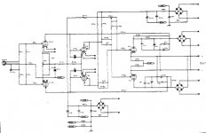
Re: Graaf GM-20
Thats the one. http://www.audiodesignguide.com/otl/graaf20.gif
this one a little bigger but just as illegible.
Audiofanatic said:
Is this the one? I foud it on the internet, can't remember where though 😎
Best regards,
Audiofanatic 😉
Thats the one. http://www.audiodesignguide.com/otl/graaf20.gif
this one a little bigger but just as illegible.
- Status
- Not open for further replies.
- Home
- Amplifiers
- Tubes / Valves
- 6C33C schematic