Think I will go with the FW since it has the slower, gentler start-up.
When I get home I will see about hooking up the transformer I have to see what the seconderies are, other then that I "ain't" got nothing to race with.
When I get home I will see about hooking up the transformer I have to see what the seconderies are, other then that I "ain't" got nothing to race with.
hi Rick - just got in from a few days at the beach so I'm clearing through some stuff - will be back to you soon!
Cheers
Cheers
hi rick - some Q's:
what's the thinking behind the 5k load resistance? In the case of this supply, I'f be more inclined to sim it with a constant current load rather than a fixed resistance. as you currently have it the current is 54mA and rising at 2 seconds. I don't think a 12a*7 is gonna love you at that...
Re-run the sim with the ACTUAL tube current (both channels) as the load. To do this, right mouseclick over the Load section and select Constant Current option. Then enter your calculated load.
Are your caps actually the same spec as what you have put?
You have got down to an (albeit simulated) very low ripple, but you could be sacrificing power supply impedance for straight line graphs. If you can get ripple to, say, 100mv no one is going to die, and you will save a lot of time!
Hey Ashton,
Hope you had a great time at the beach. After spending the last few days working on the room my wife added to the house I am ready for a few days of R & R.
As for the sim, I am still reading through two write-ups on using PSUD as I have no clue. I just read about using a constant current instead of a resistive load. I have read about ripple but have not found it. When I calculate current for the tube am I to use the Anode current or the cathode current?
Thanks
Riki
aaaaah I feel your pain vis-a-vis home maintenance. My instructions for tonight (Jos is still at our weekender at the beach...) are to coat the deck (about 20 sq metres) in just the right shade of timber stain.
I'm almost 100% sure i have chosen the wrong shade.
Anode or cathode current, it makes no difference - in your case they will be the same.
Ripple is the difference between the highest and lowest voltage once the system has stabilisied. In your first sim, it was in the order of 1's of milliamps - in effect, nothing. That occurs at the expense of LARGE caps and often high power supply impedance. 10's of milliamps is perfectly adequate in this application.
Don't underestimate the effect of the transformer data in PSUD. If you get all data accurate, the software is VERY good. If not GIGO applies.
Have a play with it - you'll get the idea pretty quickly!
Cheers
Ashton
I hear you on the color front. That is why I never pick colors unless I am brought less then 5 to pick from. I figure they are all colors she likes. Make sure you take breaks for refreshment!
I need to finish reading the two write-ups I found, I have learned a good bit about PSUD from them. Just need to play with it a bit more.
The resistors for the maggie came in, I am going to replace them and then work on the PS.
I need to finish reading the two write-ups I found, I have learned a good bit about PSUD from them. Just need to play with it a bit more.
The resistors for the maggie came in, I am going to replace them and then work on the PS.
Hi Riki - OK - the output V of your transformer is pretty high if all you need is 280VDC at 21ma.
I'm presuming that you are modelling using the default transformer specs in PSUD, not the spec of the transformer you are using.
I've posted a revision with the transformer spec voltage changed (250VAC) and the filter values changed. I've done this to get two things - lower psu operating temperature and smaller cheaper easily available components. It also performs better!
Its still a long way from perfect, but I'll leave you to optimise it for your actual transformer as that will make a significant difference!
Attachments
Ashton,
Still need to go over your file, but thought you might like this.
I have been working on a Magnavox amp, I just got it working.
Still need to go over your file, but thought you might like this.
I have been working on a Magnavox amp, I just got it working.
An externally hosted image should be here but it was not working when we last tested it.
An externally hosted image should be here but it was not working when we last tested it.
Last edited:
wooohooo! Thats way cool! What are the tubes in the output?
The rise time is fine at 1 second. If its too long it can be an indication that your power supply is going to be high impedance. Remember, 1 second is sixty cycles of the PTX, 120 phase changes. In terms of the electrons, its a lifetime.
You could get all dippy about cathode stripping blah blah, but again I refer you to the purpose of your build - to get something working and play with it to see what it does. We are not looking for finesse here, just trying to minimise the cost and the smoke.
Check out the power supply on the 'vox - I'll bet it has over a volt of ripple at hte power tubes and rises t o full voltage in less than 30 cycles. The cap will be a 40-40-20 in that can and all that is supplying maybe 150ma. By comparison, your power supply for the buffer is of medical equipment quality!
So, what does the 'vox sound like???
Output is PP 6V6.
LOL, Very well put about the rise time and true, I am not looking to destory tubes but cost and easy experimentation are top of the list.
I never thought of putting the maggie's PS in spud.
I have it hooked up to some pos speakers that I was not worried about destroying. Needless to say, I have not been able to bring myself to unhook them to try them on a better pair of speakers. So in other words," it sounds amazing, I am hooked."
I'm always happy and amazed when anything of mine works, let alone works well!
I'm constantly reminded of Woody Allan's description of the worst sex he ever had. "Fantastic"
Guess that makes me a vacuum slut.
I'm constantly reminded of Woody Allan's description of the worst sex he ever had. "Fantastic"
Guess that makes me a vacuum slut.
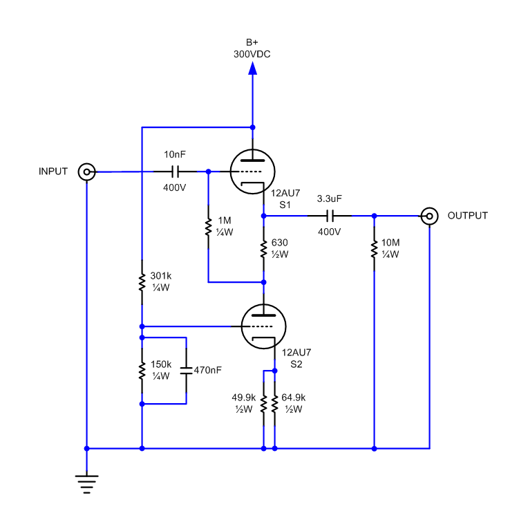
What do you think of this circuit Ashton?
An externally hosted image should be here but it was not working when we last tested it.
For grins, here is the buffer stage I have in my preamp, which is a cathode follower with an active load using a 12AU7. It's pretty much a text book implementation following MJ's approach.
More here:
Buttons – metaruss
More here:
Buttons – metaruss
Ashton,
You know it! I was just wondering what you thought of that circuit. From what I understand it is another take on the circuit you came up with for me.
Plus I was told that I don't need 280V to the anode, that 150 was more then enough for what I am looking to do.
rknize,
have you tried that circuit with less B+? Did it change the sound?
Riki
- Status
- Not open for further replies.
- Home
- Amplifiers
- Tubes / Valves
- 6BQ5/EL84 tube buffer questions