Hi all. I'm hoping to get a little advice, and know there are many of you here more knowledgeable than I 🙂
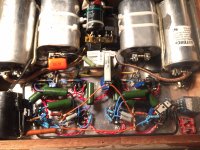
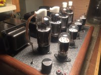
I have built from scratch this Push Pull 6BG6GA amp. Voltage amp/phase splitters are LTP, CCS, 6SN7. Drivers are simple cathode bias 6SN7. The 6BG6GA's are negative biased, with 75K grid resistors.
I am getting some oscillation problems in the 6BG6's. You know the type, blue flashing in the tube. The bias/current draw on the tube oscillates between the quiescent 45ma and about 75ma. Oscillation is at about 2Hz. It's very sensitive to the rest of the amp. Get the CCS set for too much or too little current on the first 6SN7 for example, and it oscillates. If I unhook the front end and just leave the 6BG6's hooked up just like this, at 50ma bias, they will sit there stable all day long.
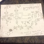
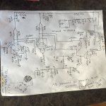
I'll post the schematic, if someone could help me cross some stuff off the list I'd be thrilled. I feel like I've checked over most of what I knew could cause it.
Things I have tried:
lower B+ (turn down variac so that b+ is only 350)...still oscillates, tubes still get blue/white "flashes"
Lower grid R's on 6BG6...I started out with 100k. 75K is much better but the problem still occurs sometimes in testing
Leaky coupling cap? Nope, they're all blocking fine.
Leaky Tube? Nope, all test NOS or better on a verified tester
In tests when I had the oscillations stopped, she sounded great...but obviously I'm not exactly sure what's causing them, or why they come and go. Like I said, it's very dependent on how the rest of the amp is set up, I.E. where do I have the CCS set, what cathode R value do I have in driver position, etc. Seems like I should be able to play with these things without sending the finals into oscillation mode, right?
Thanks all
I have built from scratch this Push Pull 6BG6GA amp. Voltage amp/phase splitters are LTP, CCS, 6SN7. Drivers are simple cathode bias 6SN7. The 6BG6GA's are negative biased, with 75K grid resistors.
I am getting some oscillation problems in the 6BG6's. You know the type, blue flashing in the tube. The bias/current draw on the tube oscillates between the quiescent 45ma and about 75ma. Oscillation is at about 2Hz. It's very sensitive to the rest of the amp. Get the CCS set for too much or too little current on the first 6SN7 for example, and it oscillates. If I unhook the front end and just leave the 6BG6's hooked up just like this, at 50ma bias, they will sit there stable all day long.
I'll post the schematic, if someone could help me cross some stuff off the list I'd be thrilled. I feel like I've checked over most of what I knew could cause it.
Things I have tried:
lower B+ (turn down variac so that b+ is only 350)...still oscillates, tubes still get blue/white "flashes"
Lower grid R's on 6BG6...I started out with 100k. 75K is much better but the problem still occurs sometimes in testing
Leaky coupling cap? Nope, they're all blocking fine.
Leaky Tube? Nope, all test NOS or better on a verified tester
In tests when I had the oscillations stopped, she sounded great...but obviously I'm not exactly sure what's causing them, or why they come and go. Like I said, it's very dependent on how the rest of the amp is set up, I.E. where do I have the CCS set, what cathode R value do I have in driver position, etc. Seems like I should be able to play with these things without sending the finals into oscillation mode, right?
Thanks all
Attachments
Last edited:
It might be in the HT supply. There is only 100 ohms separating the driver from the power section.
I experienced similar problems one time with a CLC(power section) LC(driver).
When the HT on the outputs would go down a little, the driver cap would try to compensate. This resulted in a very low frequency oscillation.
A diode fixed this reverse current: CLC(power section) diode LC(driver).
A bigger resistor than 100 ohms should work as well (and provide better filtering as well).
Perhaps the phase splitter sharing an unbypassed cathode resistor is creating a small internal feedback. Try 2 resistors. 5K.
The phase splitter is CCS
And so not sure what you mean by 2 resistors. I know in a traditional ltp with resistors in the tail, but this is a ixys cascode, and that part in particular is working fine. I can set current wherever I want and watch the voltage at cathode go up with less and down with more, just as it should....as to the previous poster the ground is all to chassis. Not most efficient but I've checked all grounds and they're good. Manufacturers got away with that for years in the 60s and 70s, still do...thank you both for the replies btw
And so not sure what you mean by 2 resistors. I know in a traditional ltp with resistors in the tail, but this is a ixys cascode, and that part in particular is working fine. I can set current wherever I want and watch the voltage at cathode go up with less and down with more, just as it should....as to the previous poster the ground is all to chassis. Not most efficient but I've checked all grounds and they're good. Manufacturers got away with that for years in the 60s and 70s, still do...thank you both for the replies btw
Thank you
Just saw the post as well on the power supply decoupling. I had thought about that, but not the diode. I'll check up on that tonight and report back. Thanks again, and please let the comments/criticism keep coming, I need it everyone.
Loren
Just saw the post as well on the power supply decoupling. I had thought about that, but not the diode. I'll check up on that tonight and report back. Thanks again, and please let the comments/criticism keep coming, I need it everyone.
Loren
And so not sure what you mean by 2 resistors. I know in a traditional ltp with resistors in the tail, but this is a ixys cascode, and that part in particular is working fine. I can set current wherever I want and watch the voltage at cathode go up with less and down with more, just as it should....as to the previous poster the ground is all to chassis. Not most efficient but I've checked all grounds and they're good. Manufacturers got away with that for years in the 60s and 70s, still do...thank you both for the replies btw
So your phase splitter is ahead of the voltage amp? And your driver grids have no grid to ground referrence.. grid leak resistors?
Last edited:
Shoot no I have to edit the schematic. The he phase splitter is also voltage amp, first stage, then drivers which yes have 220k grid leaks referencing ground, then 6bg6. I'll go edit it right now
What Parafeed said. Avoid low R resistors in the PS. 5 ohm and 100 ohm are not doing you much good. Up the values to more useful filter values.
Here is the correct schematic
Sorry about that 20 20. Here it is, with the grid leaks. Yes, input is also phase splitter. This topology is pretty often seen on 2 stage amps. I just wanted to, and like, splitting phase while the signal is still small. So I did, and then it goes to drivers. I think the topology is good, I'm just missing something. I really want to try what the poster said about decoupling the stages a bit more. I have made other amps with light decoupling like this. As long as the PS was well filtered, which it is, they were fine. But, that means nothing in this case. I know these 6BG6's are pretty sensitive to changes, especially at these voltages.
So, anyhow here's the schematic, revised to show what's actually going on now. The only time I have ever had a 2Hz oscillation problem like this was feedback problems, but I don't see where they would be coming from.
What is it that causes the blue flash? I'm familiar with common blue glow, from imperfections in the vacuum of the tube. But when these are running without the oscillations there is no glow. As soon as they start to oscillate they flash a light blue, looks like it's coming from in between the cathode and the grid, or grid and control grid....
Attachments
Ok, I will. For the drivers. Also I will try the diode, if the larger R doesn't work. For the Power section they are not hurting though, are they? I didn't want to drop any voltage there, I just figured that cap, 5 ohm, cap after the initial CLC would be better than just paralleling caps?
I did, in psud the ripple is pretty much gone after the initial CLC, then, placing more RC filters even with small R values just reduces it more. It doesn't seem that 3 or 5 or any small ohm value RC to the finals would do any harm. But yes I could see that only 100 ohm on the branch to the drivers could be an issue. I wanted to keep the B+ as high as possible for the drivers and drop it in the plate R's to keep the load lines nice, seeing as how the drivers are not CCS. Another strange thing was that the cascode mosfet CCS works great in the tail of the input/phase splitter, even with just those few volts. But I tried the exact same CCS on the tail of the drivers with no success?
Yes
Yes the 6BG6's flash right along with the bias/current oscillating.
What happens is the amp comes on, starts to warm up. You watch the bias (I'm measuring Mv on the 10 ohm at cathode to ground) and it comes up to 45-50 ma (where I have it set) Then, after a few seconds of warming up a bit more the meter will suddenly jump and the oscillation has started. Now were going between 45-80ma. Depending on how I have the rest of the circuit set (I'm still playing with OP points for the input and drivers) the oscillations can be anywhere from small flashes that you only see if you look closely in the dark, to bigger flashes accompanied by a clicking (arcing) coming from the 6g6's.
What always stays the same is the frequency. Always at about 2Hz. Always all the 6BG6's. Always a blue/white flash coming from inside the plate structure. This is not the "blue gas cool glow" kind of thing.
Yes the 6BG6's flash right along with the bias/current oscillating.
What always stays the same is the frequency. Always at about 2Hz. Always all the 6BG6's. Always a blue/white flash coming from inside the plate structure. This is not the "blue gas cool glow" kind of thing.
Ok. I'm looking at all the symbols for your caps that you've drawn and see they are all the same, even the bias caps whose polarity should be (+) grounded. Checked, and double checked? Also, not being familiar with the output tubes you're using I'm seeing what seems to be kind of low grid resistance through the bias supply, about 80K... I would expect to see about 250K through there. Have you ever had more than 75K to the grids? Also, are those little bias bypas .01 caps an attempt to stop the oscillations which had no affect or just original to the design? You have 40 tons of filtering where 100 lbs. will do. I'm just leaning to a high cathode to grid current that has to go somewhere if the oscillation drives the grid (+). It's too close to gound with all the filtering and low impedance too. Just a theory.
Sorry again about the schematic but yes, the caps in the bias supply are the ONLY electrolytic in the whole thing, and yes checked and double checked, + to ground....the .01's were indeed an addition, I just like to have a well filtered bias supply even though I realize you can get away without it a lot (look at some old single diode designs). The grids....6BG6ga data sheet calls for no more than 100k on fixed bias. I started with 120, wanting the drivers to be feeding high impedance and thinking I could fudge the data sheet a bit. Wrong. So I went down to 75K there. That helped, but it obviously wasn't the main problem as the oscillations are still occurring.
One thing strange to note is that if I take the input tubes out of socket, problem still happens. But if I disconnect B+ from the 4.3K dropping resistor it stops. So I thought "well, with that power hooked up the ONLY connection to the rest of the amp is the plate resistors and coupling caps in the inputs, so I must have some, or a, leaky coupling cap letting some DC through to the drivers.....NOPE! All caps are fine, checked, and double checked on a scope. So, why would it matter wether power was going to a 4.3k dropper and some plate resistors, when there is no tube in the socket pulling any current...
Put the input tubes back in and you can stop the oscillations ONCE YOU GET THE INPUT TUBES TO THE RIGHT OP POINT. But, I should be able to change OP points of the input, and of the drivers, all over the place while I experiment, WITHOUT sending the finals into oscillation.
I'd still like to know, what actually causes the blue arcing/flashing that comes from within the plate structure and happens in sync with the oscillations?
Thanks much again for all the replies.
This doesn't address your oscillation problem, but why aren't you using a CCS under the second LTP? 2.5K isn't very much of a tail impedance. Also, the grid bias voltage of a 6SN7 @5mA/side is only about 3.5V. Not very much "headroom" for a decent CCS. If you added a small negative supply (simple choke input with schottky bridge and cap) about -20V you could use BJT cascode CCSs which would greatly enhance the performance of the LTPs and improve the SQ.
Yes John, I agree, and I plan on adding it. I have a 5V tap unused that I am going to add a small transformer reversed, then rectify, etc...so yes I will, thank you, but for now it's enough voltage to keep the CCS working at least. Not going for SQ yet, just to get it to work.
As for the second pair...it's not a log tailed pair. It's just a common cathode differential. Phase is split by the first LTP, the second stage is just 2 drivers that share a cathode for balance. I tried the same exact CCS circuit there but it wouldn't hold? Maybe I will be able to get it to work there after I make the neg. supply. But still, doesn't seem that that is what is causing the problem as the problem can and will occur without even having a tube in socket of the first stage.
Loren
What you have drawn is a differential LTP (you need a grid leak resistors on both grids). With the B+ you have available you could direct couple the driver stage to the input stage, eliminating the coupling caps to the input stage (then no grid leak resistors). There would also be plenty of voltage available from the common cathode of the second stage to ground for a CCS. Just make sure that the driver stage has enough voltage swing and a little extra to drive the output stage to clipping (output clips before driver). If that is deficient in the case of direct coupling you could load the driver with a CT plate choke (good ones are expensive :~( though). The choke will swing almost twice the B+ voltage.
If you have more than enough gain with this design I would also consider using a driver tube with a lower Rp. IME a 6SN7 driver doesn't quite get the job done when it comes to providing a good "boogey" factor.
If you have more than enough gain with this design I would also consider using a driver tube with a lower Rp. IME a 6SN7 driver doesn't quite get the job done when it comes to providing a good "boogey" factor.
- Status
- Not open for further replies.
- Home
- Amplifiers
- Tubes / Valves
- 6BG6GA PP, -bias, Amp built but couple problems