according to the datasheet: Rg should be 100k (max)
rk should be somewhere between 1500 and 2k
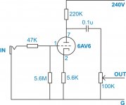
did a quick drawing; if you want -1v at grid and use 220k ra, you should use 1785ohm, for a gain of 71x (va will be around 100v)
with Rk being so high, the tube is in cut off, drawing too much current (about 3,13ma)
rk should be somewhere between 1500 and 2k
did a quick drawing; if you want -1v at grid and use 220k ra, you should use 1785ohm, for a gain of 71x (va will be around 100v)
with Rk being so high, the tube is in cut off, drawing too much current (about 3,13ma)
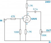
You want the plate resistor to be higher, maybe 200k or so. With the 100k pot as load, the effective plate load is about 67k. That will keep the gain increase to something reasonable.
If that doesn't give you enough gain, there are some tricks you can play in the cathode circuit, but try the easy circuit first.
If that doesn't give you enough gain, there are some tricks you can play in the cathode circuit, but try the easy circuit first.
Ra needs to be 220k, for the rest it looks quite allright.
you can use a 1,8k for rk, it won't matter much.....
what is the load the 6av6 is working in?? (eg. the next stage's gridresistor)???
the amplification (71x) is now only calculated without taking in the calculation the load.
AND i forgot the cathode resistor (1,8k) would need a capacitor in parrallel (2,9uF minimum).
The stage will work without ck of course, but then the amplification will be somewhat less
An unbypassed cathode will provide gain that is some fraction
of the mu of the tube... If you were to add an electrolytic bypass
cap on the cathode, you'd get the full mu (gain) of the tube.
Gain = mu * (Reff / Rload + Reff)
Reff is the sum of the Ra of the tube, and the reflected cathode
resistors impedance through the mu of the tube, in other words:
Reff = Ra + (mu+1)*Rk
You need to twiddle the values of Rload (the anode resistor)
and Rk (the cathode resistor) around the fixed parameters mu,
Ra, to get the gain to want..... Time to fire up the calculator
and work up a table of values.
Best!
-- Jim
ooops. Didnt see the 100K pot!
I should have been more careful looking at your schematic.
I think the problem is the the effective plate impedance of the
tube is close of the load impedances (100K pot). In this
scenario, the output circuit is always acting as an attenuator
because the 100K pot is too heavily loading the tubes Zout.
You probably need to use a second triode as a cathode follower
stage to provide a lower impedance source to drive the potentiometer and cable.... i.e. ECC82, ECC81. If this isnt possible, then a tube with high mu and lower Ra is needed.
How about 6AK5, 8532, 6J4, etc...
-- Jim
hi all 🙁
it didn t work again 🙁
i leave plate resistor ( connected to pin 7 ) 220k
, remove the 100 k pot and change the rest just like the values i shown in second schematic 🙁
when ii connect my signal generator a very small signal comin up from out put ( almost half of the original gain )
and when i connect my bass , nothin comin out ! 🙁
Have you measured the dc voltages present in your pre-amplifier circuit to make sure it is working? I will admit to having mis-wired a tube socket once or twice, check to make sure that you haven't done the same - a lot of symptoms you describe could be due to a simple wiring error.
How about the input jack/wiring you are using?
How about the input jack/wiring you are using?
- Status
- Not open for further replies.
- Home
- Amplifiers
- Tubes / Valves
- 6av6 mini pre didn t work