Hi
I am trying to troubleshoot a stereo amp with one dead channel.
I have found that I have 5 VDC on the plate (pin 5) of the problem 6AU6 and
2.5VDC on the Cathode(pin 7)
Pin 6 has a very high voltage (compared to the other tube) of 100 VDC.
The working channel has only about 30VDC on pin 6 and 100VDC at pin 5
I have replaced all the relevant resistors checked the tube socket, ground connections, the DC supply is fine at 243VDC.
The 6ufd bypass cap seems OK and everything is wired the same as the working channel.
I have swapped tubes all with the same result.
Help!
Attachments
Cathode and plate voltages imply the tube is idling much hotter than the good side. Is there dc voltage on pin 1? Maybe the input control's wiper is bad?
I agree with jjman. Try putting a 1 megohm resistor between pins 1 and 7 and see if the voltages return to normal. That resistor should really be there as a safety net if the pot fails.
Gary
Gary
No Effect
Tried the 1MΩ resistor and it had no effect.
I just don't understand why this tube would not be conducting.
Tried the 1MΩ resistor and it had no effect.
I just don't understand why this tube would not be conducting.
It's conducting like crazy, it pulls its anode voltage all the way down...could you measure the dc offset on pin 1 as jjman suggested?
Well, like crazy...2.4mA. But a lot more than the other channel, that's for sure.
Well, like crazy...2.4mA. But a lot more than the other channel, that's for sure.
Last edited:
The working channel has only about 30VDC on pin 6 and 100VDC at pin 5
The 680 kohm resistor from supply to screen must be wrong (small).
Check this again.
If it is OK, then take the tube away from the socket and measure the voltages then.
More likely the 470 resistor from p6 to ground is O/c.
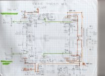
Strange circuit, why is the tone control within the overall loop? put it in the negative feedback circuit by all means, but where it is the neg Fb will be fighting it....
Strange circuit, why is the tone control within the overall loop? put it in the negative feedback circuit by all means, but where it is the neg Fb will be fighting it....
More likely the 470 resistor from p6 to ground is O/c.
I am not aware what "O/c"-means, but if it means "open",
still the anode current of 6AU6 should not go to "top" and anode voltage to almost zero.
But let's see after Glowin Plates has tested.
Sorry O/c normally refers to open circuit.
From experience, high value resistors tend to go open rather than low value, but in this case it is possible that the 680K has gone low.
The measurements do tend to support this, the anode is conducting c. 1.2mA and the cathode c.2.4mA so where's the other 1.2mA coming from?
From experience, high value resistors tend to go open rather than low value, but in this case it is possible that the 680K has gone low.
The measurements do tend to support this, the anode is conducting c. 1.2mA and the cathode c.2.4mA so where's the other 1.2mA coming from?
It almost seems as if this circuit was designed to use an EF86, judging by the apparently intended bias point. Seems to me that running a 6AU6 in this fashion would lead to unpredictable behavior and bad overall performance (both gain and distortion). I could be talking out of my behind though; just theorizing out loud here.
GP, are you sure you got all the values right in that diagram? Are the tubes the original complement?
GP, are you sure you got all the values right in that diagram? Are the tubes the original complement?
I was just thinking about that; I can only come up with the grid, but that would require a couple hundred volts of DC on the volume pot. So we're missing something.The measurements do tend to support this, the anode is conducting c. 1.2mA and the cathode c.2.4mA so where's the other 1.2mA coming from?
A rough calculation predicts the screen resistor (680K) has shifted to around 100K.
Interesting to see what has really happened.....
Interesting to see what has really happened.....
If there was positive volts on the control grid, this would also pull the screen grid down.
The 6AU6 is a 7 pin valve so clearly not intended for an EF86. more usual place to find this valve is in IF strips but as it's not variable mu then perfectly Ok for audio.
The 6AU6 is a 7 pin valve so clearly not intended for an EF86. more usual place to find this valve is in IF strips but as it's not variable mu then perfectly Ok for audio.
The 6AU6 is a 7 pin valve so clearly not intended for an EF86. more usual place to find this valve is in IF strips but as it's not variable mu then perfectly Ok for audio.
6AU6 is really a very good tube for audio circuits. Also as triode connected. It was quite common before EF86 appeared.
It was also used in low noise mic. amplifiers so that the screen was connected as an anode and anode connected to ground to form a shield around other electrodes.
I'm not suggesting they shouldn't be ok for audio, but the operating point chosen here seems a bit odd to me.The 6AU6 is a 7 pin valve so clearly not intended for an EF86. more usual place to find this valve is in IF strips but as it's not variable mu then perfectly Ok for audio.
Strange circuit, why is the tone control within the overall loop?
Really. I just now looked at the schematic better.
The tone control can not be inside the NFB-loop.
The whole desing needs some "adjustment".
Hi Glowin.
Have you found the offending part yet, we're all dying to find out what it was?
Regards
Henry
Have you found the offending part yet, we're all dying to find out what it was?
Regards
Henry
Problem solved
Hi Guys
Yes I found the problem was the plate resistor which I had allready replaced once
and I suppose damaged. Though it looked normal and even measured OK.
After replacing it I had voltage on the plate again.
I also had a weak tube so after replacing that, things were even better
and now I have a healthy 120 VDC on both plates.
I'm sure your right about the tone circuit however this is just an el cheapo console stereo you could buy at Sears in the mid 60's.
(I actually found a date code of 1960 on one of the caps).
I thought it was a great find for $20 though.
And it sounds pretty good for what it is.
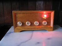
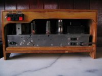
I have attached a couple photos of the amp and cabinet I made for it.
Thanks for everyones help.
Hi Guys
Yes I found the problem was the plate resistor which I had allready replaced once
and I suppose damaged. Though it looked normal and even measured OK.
After replacing it I had voltage on the plate again.
I also had a weak tube so after replacing that, things were even better
and now I have a healthy 120 VDC on both plates.
I'm sure your right about the tone circuit however this is just an el cheapo console stereo you could buy at Sears in the mid 60's.
(I actually found a date code of 1960 on one of the caps).
I thought it was a great find for $20 though.
And it sounds pretty good for what it is.
I have attached a couple photos of the amp and cabinet I made for it.
Thanks for everyones help.
Attachments
Last edited:
- Status
- Not open for further replies.
- Home
- Amplifiers
- Tubes / Valves
- 6AU6 preamp problem