6au5gt
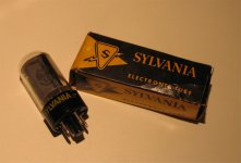
I just saw a little collection of NOS 6AU5GT Sylvania's in the old boxes and stamped USA on the glass. I purchased one to take home and fiddle with.
Have you seen any SE or Push Pull designs using this handsome little TV tube? I bet it would make sweet audio? Any comments would be great!
Cheers,
Shawn.
Attachments
I had some RCA 6AU5GT. they are design as power tube, but I can't found any schematic on web. maybe you should design by yourself, I think its not diffcult to built ibut dosent mean sounds good.
Sam
Sam
http://www.diyaudio.com/forums/showthread.php?threadid=37403&highlight=
http://www.diyaudio.com/forums/showthread.php?threadid=74650&highlight=
Edit: Ooops, 6AU5 and 6AV5 ain´t exactly the same thing, but close.
http://www.diyaudio.com/forums/showthread.php?threadid=74650&highlight=
Edit: Ooops, 6AU5 and 6AV5 ain´t exactly the same thing, but close.
I found one 6AU5, and tried it during the 6AV5 experiments (same pinout) mentioned in the previous post. I didn't push it hard enough to find its limits because I only had one and it looked well used.
You should be able to use these in a generic triode wired SE amplifier, but I don't know how much B+ you can get away with since the screen grid is only rated at 200 volts. I think this tube would work well in screen driven P-P applications. This seems to be the best application for a 6AV5.
The DeHaviland 845 SE amplifier used a 6AV5 for the driver in early units and then switched to a 6AU5, because "it sounds better".
Beam Power
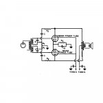
OK Tubelab, testing shows best result in Push pull? Inside the pdf from P.Millett's site "Beam Power Tubes" by O.H.Schade(thanks sam8888ysl ) I found the basic set up(see attached).
I cracked the pdf with Photoshop and tried to open up the diagram so if you need to scribble on top, you will have more room. 😉
Am I getting somewhere?
Shawn.
Attachments

Power supply
Do we really need B+ of 300 and 400 volts? Can this be reduced to a single supply?
Would the circuit function better with -negative bias instead of ground?
I read in the pdf previous that the Beam Tube circuits requires only 10% or less in feedback?
Give me some more feedback and I will try to draw a proper schematic when I get back home tonight. My goal is small power with low distortion.
Thank you very much for the input so far, perhaps we have a new amp brewing here?
Cheers,
Shawn.
Sylvania Data Sheet
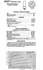
I extracted the data from PMillett's posted Sylvania 1951 guide on the 6AU5GT ( these are the ones I have access to) and reduced in to a one page data sheet.
Does this help the situation? It is rough and I have a higher rez so email me and I'll send it to you or brouse it youself by downloading from P.Millett's site. It is in the 1951 Sylvania pdf.
Shawn.
Also, here is a link to a bigger image.
Attachments
Post 7 Pre Drive Phase Splitter
Hmmm, I think the schematic posted in Post7 is too complex for such a small amplifier and it may have too high a drive capability, that may not be required in a small vacuum amplifier.
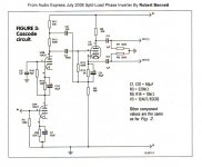
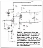
Reading over again, the article posted in the July 2006 Audio Xpress issue, I may need to stick to tried and true? Also posted in this artical the following image from Robert Bennett.
Hmmm, I think the schematic posted in Post7 is too complex for such a small amplifier and it may have too high a drive capability, that may not be required in a small vacuum amplifier.
Reading over again, the article posted in the July 2006 Audio Xpress issue, I may need to stick to tried and true? Also posted in this artical the following image from Robert Bennett.
Attachments
Audio Xpress content
I sent an email to verify if it is ok to publish scans from their(Audio Xpress) July issue, here in the DIY.
Regards,
Shawn.
I sent an email to verify if it is ok to publish scans from their(Audio Xpress) July issue, here in the DIY.
Regards,
Shawn.
Amplifier Mode
Duh, I guess if I change the supply to the output section from one source, I change to the mode of operation?
Duh, I guess if I change the supply to the output section from one source, I change to the mode of operation?
When you choose a unique tube, you must be prepared to do some experimenting, and possibly offer a few tubes up to science to find out what the limits are.
When I went down the 6AV5 road I tested several tubes to find out how much screen voltage and plate dissipation that I could run without melting tubes. This proved that I could safely overdrive the screen grid, but the safe plate dissipation varied from 15 watts to almost 30 watts depending on which brand and vintage tubes that I tested. Most of the tubes that I have are of the 15 watt variety.
SE operation, by definition must run class A which means a lot of plate dissipation. A good SE amp will put out about 25% of its dissipation rating. I don't need another 4 watt amp, so I looked to push pull. You may get 3 or 4 watts from a 6AU5 in SE. If this is sufficient, don't rule it out.
I could have built a conventional push pull amp with the 6AV5, and you can probably do the same with the 6AU5. Look for a circuit that uses 6V6's or possibly EL84's. Some tweaking of the voltages and component values will be needed.
I wanted to maximize the power output of the 6AV5's, and exploit their unique characteristics, so I looked for something different. A few people have used sweep tubes (tubes made for horizontal output duty in a TV set) succesfully in screen driven applications (drive applied to G2 instead of G1). The advantages of this are near class B operation with good linearity. Why run class B? Very low static dissipation (tubes will last forever), and the high peak capability of sweep tubes mean a lot of power output (I get 80 watts from a pair of 6AV5's). I needed a lot of B+ to get this power though (550 volts). My amp design is still sitting on the breadboard waiting for me to finish it. I have too many projects, and not enough time. The design is not trivial since the driver must source a lot of current (I used mosfets) and swing several hundred volts. Here I was experimenting with a relatively undeveloped design using an unknown tube. You can't get a schematic for this one on the web. This calls for a lot of experimenting before you get good results. Be warned if you go down this road.
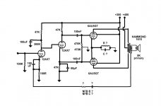
I don't see any thing obviously wrong. Some resistor values may need to be tweaked. Keep in mind that the maximum screen grid voltage is listed as 200 volts. You have it connected to a 300 volt supply. The cathode voltage will be about 30 volts. This puts about 270 on the screen. This may be OK, but you will have to look at the screen grid wires carefully in a dark room. If they are glowing red, back off the voltage, or the tube won't live long.
The cathode resistor will need to be determined experimentally. Start with about 500 ohms.
Sweep tubes have a tendency to oscillate. Add a small resistor (100 ohms or so) in series with the screen grid and the control grid, mounted as close to the tube socket as posible.
The cathode resistor will need to be determined experimentally. Start with about 500 ohms.
Sweep tubes have a tendency to oscillate. Add a small resistor (100 ohms or so) in series with the screen grid and the control grid, mounted as close to the tube socket as posible.
I just take a look, maybe you can try lower voltage. maby plate 120V -15V for grid1 screen for 150V. and with 2k OPT with 1K CT. you may got 5W output but much linear and much openness in hearing althought higher voltage got more power.
More changes
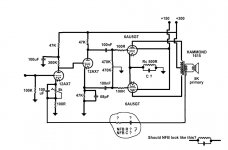
I agree fully Tubelab, this will need to hit the bench for a reality check and perhaps a little destruction but I will try to avoid it by getting as much done here as I can.
sam8888ysl, dropping the voltage significantly and using a lower impedance output XFMR may do the trick too. Much lower output potential in watts than driving the higher voltages? But perhaps lower distortion?
I lowered some voltages and added some resistors and added the adjustable pot for bias adjust on the front end.
Still, I'm very flexible and the more ideas I have heading in to the bench, the better 🙂
Attachments
- Status
- Not open for further replies.
- Home
- Amplifiers
- Tubes / Valves
- 6AU5GT