
aha got it.. so about a 5K-6K load line?^
|
It's a Class A SE loadline. Since the Q-point is 40mA, the max current is limited to 80mAmax, and a Vpk= 22.96V. When the final just hits cutoff, the voltage will be 485.29Vmax. That gives a current swing of 80mAp-p -- the outer limit of Class A. A Class B, PP loadline would start at 250V since the PP pair conduct on alternate cycles, and the PP OPT operates on differential current only.
Class AB PP would require a load of 24K/P-2-P, and Class A PP 12K/P-2-P as it would be a balanced, two-phase source. As given, the OPT needs to match 6000 : 8 for one section or 3000 : 8 for paralleled sections (or whatever your speeks are).
so 250v 40mA 5K-6K or 250v 50mA 3.5K (per section) ??
Of course I probably will include 6db of switchable feedback.
Of course I probably will include 6db of switchable feedback.
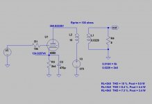
Here you can see different load resistances and their effect to THD and Pout.so 250v 40mA 5K-6K or 250v 50mA 3.5K (per section) ??
Attachments
That's for one half of the 6AS7aha got it.. so about a 5K-6K load line?
yes... the assumption was only half of the 6AS7G. Will parallel if needed and half the load impedance.That's for one half of the 6AS7
Has anyone tried different primary impedances and current levels to attest to the difference in sound? Just curious.
Thanks!
Thanks!
@artosalo - I know it's 2 years old thread, but I was wondering if you still have LTSpice model for 6as7 in parallel connection as you shown in your post? Would it be possible to share the file? I have 5k impedance output transformers and 3W is far enough for me. Would be happy to experiment with this amp. I am thinking to add LM317 based current sink in cathode, as I heard 6AS7 if notoriously floating and match them fir stereo seems to be challenging. Your LTspice model would be great start for me. Thank you in advance!Attached one version. If you need the LT Spice .asc, let me know.
Simulations are great to get an idea of whether the circuit works or not.
Tube models are rather good. But a good model of the bends in an OPT model are a problem.
Bottom line, the D% the simulation calculates is often assuming a perfect OPT.
Just includes resistances . And reactances near the moving operating point.
Gotta build it, then measure the result.🙂
Tube models are rather good. But a good model of the bends in an OPT model are a problem.
Bottom line, the D% the simulation calculates is often assuming a perfect OPT.
Just includes resistances . And reactances near the moving operating point.
Gotta build it, then measure the result.🙂
@artosalo - from your post from 2022.02.17 I understood your made such amp with speaker transformer coming from Toroidy.pl. Impedance applied to PARALLEL 6AS7 was 1,65k. Is that correct? From our earlier conversation I understood that transformer of 5k primary will bring me to around 3,7W at 8ohm, correct? Having all above in mind is it right assumption that using 6AS7 in parallel with 2,5k (2500ohm) transformer with put me somewhere around 7W of power to 8ohm? Reason I ask is 1/. 2,5k transformer is something I have in hand 2/. I am looking to replace my SE EL84 5W with something real triode, so everything between 5-7W makes me full happy 😊Simulation shows 3.7 W with 0.3 % THD.
Yes, with 357 V as +Ub you get some 7 W.is it right assumption that using 6AS7 in parallel with 2,5k (2500ohm) transformer with put me somewhere around 7W of power to 8ohm?
- Home
- Amplifiers
- Tubes / Valves
- 6AS7G SE output stage operating point?