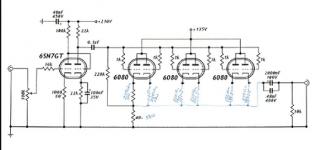
Attached is a schematic posted here a few years back from I believe Joel on a single ended OTL using 6080/6AS7's driven by a single 6SN7. Has anyone built this? I am thinking about giving it a go. The only real change I would think to make right off the bat is to give each cathode a resistor as I am under the impression that the 6080/6AS7 should have each cathode held to current on its own. Does anyone else have any thoughts?
Thanks,
Thanks,
Attachments
My only suggestion is to make sure you sink those cathode resistors well. They will get VERY hot.
I have built a very similar design, and it sounds great. I think you'll love it.
I have built a very similar design, and it sounds great. I think you'll love it.
I have been thinking of building a variant of this.
How would you couple the output to seperate cathode resistors?
What about the grid bias?
Andy
How would you couple the output to seperate cathode resistors?
What about the grid bias?
Andy
I would put a 250ohm resistor on each cathode and tie the base of each together. I parallel that gets me to 41.3 ohms and the original schematic shows 40ohms for the top resistor. then i would go and attach that to the final 40ohm resistor to ground and tie the grid resistor in between as originally designed. I will drawin it up and post it.
Thx
Thx
Do either of you gents have the schematics for the OTL's you discuss in your responses to my post?
I will pot my marked up schematic in a few hours.
Thanks,
I will pot my marked up schematic in a few hours.
Thanks,
Do either of you gents have the schematics for the OTL's you discuss in your responses to my post?
I'll second that interest. BTW the schematic desperateaudio posted emerged from this thread: http://www.diyaudio.com/forums/showthread.php?s=&threadid=5418&perpage=25&pagenumber=6
Simon
Yes that is where I got it from. I have an email into Joel to see if he ever built it but no response as of yet. I will post the marked up schematic with the resistor change in the AM as I had an emergency at home.
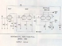
The circuit I was thinking about is the one with a cathode choke. I think it is in that thread although not a very clear picture. It dates from the '50s.
http://www.audiodesignguide.com/otl/otlse.jpg
Andy
http://www.audiodesignguide.com/otl/otlse.jpg
Andy
Yeah a few people had raised some problems with that design which i was unable to completely figure out so i decided on the one i attached. The minute i can get into work here today i will post the schematic revisions for comment.
JBLoudg20 do you have the schematic of your's?
Thx in advance.
JBLoudg20 do you have the schematic of your's?
Thx in advance.
I have read several reports (where?) from people that this design does work. ( http://www.audiodesignguide.com/otl/otlse.jpg )
On your proposal, where is the output cap going to be fixed??
Andy
On your proposal, where is the output cap going to be fixed??
Andy
Here is another one
http://www.diyaudio.com/forums/showthread.php?s=&threadid=132288&highlight=6s19p
Erik
http://www.diyaudio.com/forums/showthread.php?s=&threadid=132288&highlight=6s19p
Erik
here is the revised schematic showing how i plan to implement the cathode resistors in parallel. Again I stated earlier I have read that 6AS7's need to have separate resitors on each side of the triode to keep the current in check for the tube overall.
Any comments?
Thx
Any comments?
Thx
Attachments
desperateaudio said:here is the revised schematic showing how i plan to implement the cathode resistors in parallel. Again I stated earlier I have read that 6AS7's need to have separate resitors on each side of the triode to keep the current in check for the tube overall.
Any comments?
Thx
The large value of the cathode resistors chosen ( even though they are in parallel ) will severely reduce the output !!
Even if reduced to, say, 10ohms each, as in a previous post, the output would still be reduced.
Andy
Attachments
Instead of using cathode resistors to equalize the current draw
could you use a plate resistor on each tube? I saw this done
in the RCA receiving tube manual where a 160 ohm pot was
used to ballence the current through both halves of a 6080?
could you use a plate resistor on each tube? I saw this done
in the RCA receiving tube manual where a 160 ohm pot was
used to ballence the current through both halves of a 6080?
desperateaudio said:here is the revised schematic showing how i plan to implement the cathode resistors in parallel. Again I stated earlier I have read that 6AS7's need to have separate resitors on each side of the triode to keep the current in check for the tube overall.
Any comments?
Thx
The large value of the cathode resistors chosen ( even though they are in parallel ) will severely reduce the output !!
Even if reduced to, say, 10ohms each, as in a previous post, the output would still be reduced.
Andy
?? Looks fine to me.The large value of the cathode resistors chosen ( even though they are in parallel ) will severely reduce the output !!
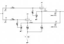
I think the implementation of a cathode choke should be worthwile (raising cost with about 60$ using Hammonds), requiring lower B+ and also (more importantly, or am I mistaken?) raising efficiency. Here's a similar circuit: http://vincent.brient.free.fr/otl7w_fr.htm
Regards - Simon
To make this cicuit work you have to take out max currents through the 6080s which means their workingpoint should be Ia 125mA, Ua 100V.
You should also use a choke or a CCS from the cathodes to ground. A B+ of 130-170V will do.
Every triode has an theoretical (simplified 1/Gm)Rout of ca 140ohms, so adding a separate 10 ohm to each one will not make you loose so much. Without NFB Zout will be high anyway.
If going for a 8ohm load I would suggest using at least 5 but preferably 10 6080s/channel.
Klimon said:?? Looks fine to me.
I think the implementation of a cathode choke should be worthwile (raising cost with about 60$ using Hammonds), requiring lower B+ and also (more importantly, or am I mistaken?) raising efficiency. Here's a similar circuit: http://vincent.brient.free.fr/otl7w_fr.htm
Regards - Simon
A cathode choke would improve efficiency.
Your circuit (see below) has the output taken via several caps from the cathode not from the junction of the resistors so the output power would be 'unaffected'.
Also the biasing is different.
I think what is needed is a combination of designs.
Andy
Attachments
- Status
- Not open for further replies.
- Home
- Amplifiers
- Tubes / Valves
- 6as7/6080 Se Otl