Hello there,
I've just completed my take on a 6AF11 champ type guitar amp (see attached.)
I thought it sounded like muddy garbage until I plugged in a guitar pedal with a buffered output.
I thought "huh, the cable im using must have too much parasitic capacitance!" So I tried using a short 6" jumper cable straight from my guitar to the input jack.
No dice.
I have a pedal testing rig with a switchable buffer, and no matter how much cable length I added, turning on the buffer would make it sound good again.
Then I tried removing the capacitor between the grid and cathode of the input triode. Nothing changed. I thought for sure it was the interelectrode capacitance shunting high frequencies. Nope.
I'm now planning on adding a built in mosfet buffer circuit to go in front of the first triode, but I can't help but feel that I'm missing something.
Any ideas?
Attachments
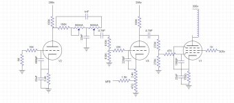
Does the 1M resistor at the input of your amp actually measure 1 Meg?
I'd leave out the 680p cap anyway as it lowers and damps the PU resonance.
I'd leave out the 680p cap anyway as it lowers and damps the PU resonance.
Yup, and not just across the resistor but from the grid to ground.Does the 1M resistor at the input of your amp actually measure 1 Meg?
I have that there to get a roll off around 20k to keep out rf without needing to introduce more noise through a large resistor.I'd leave out the 680p cap anyway as it lowers and damps the PU resonance.
Heres something, the wires from the output jack for nfb go very close to the input jack. Could this be decreasing input impedence through parasitics?
Yes, I figured.I have that there to get a roll off around 20k to keep out rf without needing to introduce more noise through a large resistor.
But using only a 33k without cap is much better regarding PU sound.
Don't forget that an input tube itself typically has an input capacitance around 150p due to Miller effect.
So with the cap you're adding around 800p to the cable capacitance, which significantly dulls the sound.
You could try using shielded cable for both input and NFB wires.Heres something, the wires from the output jack for nfb go very close to the input jack. Could this be decreasing input impedence through parasitics?
Yeah I hear you. After removing the cap there was no audible difference.Don't forget that an input tube itself typically has an input capacitance around 150p due to Miller effect.
So with the cap you're adding around 800p to the cable capacitance, which significantly dulls the sound.
I'll try the shielded cable on the NFB leads.
Could be oscillating - lots of gain, input and output less than an inch apart (on the tube). Buffer is a near short for AC at the input. Blue wire on OPT (plate) should be the inside of the winding; B+ end acts as a shield.
Those resistors that connect to the 3 control grids, g1, are Not grid stopper resistors.
They can not perform that function, because there are capacitors from the 3 control grids to their respective cathodes.
A grid stopper has to be the only thing that connects to the control grid.
The idea is to isolate g1 from any parasitic C, and from any parasitic L.
The only parasitic C is across the resistor, due to the close space of the end caps.
The only parasitic L is the very short wire that connects the grid stopper resistor directly to the socket tab.
If you want to use grid stopper resistors, they need to connect to the g1 socket tab; and the other end needs to connect to the capacitors that have their other end to the cathodes.
$0.03
adjusted for inflation
Yeah I had to increase cg + CK to prevent oscillation. It was a compromise.
Maybe I'm missing something, but how does this relate to the low input impedance of the first triode?
Maybe I'm missing something, but how does this relate to the low input impedance of the first triode?
Approximation of the input circuit:
The 680pF cap on g1, connects to the cathode bypass cap to ground. The cathode bypass cap is a dead short, compared to 680pF.
680pF Xc, is 11,700 Ohms to ground.
That is in series with the 10k input resistor.
The phase of 10k Ohms and 11.7k Ohms Xc in series is close to 45 degrees Lag at 20kHz.
We have approximately 14k Ohms to ground at the input.
The -3dB is at approximately 20kHz.
14k Ohms at 20kHz to ground is Not a high impedance input.
It is approximately 140k Ohms at 2kHz.
I hope that explains it.
$0.03
adjusted for inflation.
I've already explained that removing this cap does not change anything about the response.14k Ohms at 20kHz to ground is Not a high impedance input.
It is approximately 140k Ohms at 2kHz.
You have 3 low pass filters, one right after the other.
With the tone control, there is a severe low pass filter too.
R x C product
10k & 680pF = 6.8 us
22k & 220pf = 4.84us
47k & 100pF = 4.7us
Remove one of these, very little difference
Remove two of these, a little difference
Remove all 3 of these, big difference
And, depending on the position of the two 500k tone controls, you have one more low pass filter.
The Worst Case positions are the left wiper all the way to the left, and the right wiper all the way to the left.
That essentially is 150k in parallel with 500k = 115k Ohms.
R x C product
150k & 22nF = 3300us
Wow! This low pass filter "Takes the Cake"
Watch the position of the two 500k pots, before you measure the high-frequency and mid-frequency roll off.
And, the idea of properly installed grid stopper resistors that connect the other circuitry to the g1 socket tab is a real good idea.
Improperly wired grid stopper resistors can not stop oscillations.
Certain oscillations are not heard directly, but they cause distortion of the audio signal.
Yep, this was the intention. The amp has basically no clean headroom so instead of a traditional volume control I'm using this notch filter to remove some of the muddy low mid frequency response. The left pot controls where the notch is, and the right pot acts like a gain/tone control.Wow! This low pass filter "Takes the Cake"
Watch the position of the two 500k pots, before you measure the high-frequency and mid-frequency roll off.
I ended up removing all of the grid to cathode capacitors and it did not change the fact then when not driven by a low impedance, the input sounds muddy and distorted.
I think the source impedance of the guitar pickup must be causing oscillation somehow in the first triode stage. Seems like it would be a complicated thing to model and analyze.
Maybe providing sound clips would help explain what I'm experiencing. I'll try to record some soon.
Up to now there's no real evidence of a "low" input impedance of the amp.
Particularly without the 680p shunt cap, the schematic shows a high (1M) input like many similar guitar amps.
A typical magnetic PU is a complex high impedance source.
It can be modelled as a voltage source (EMF) with a series inductance of 2H to 5H, a series resistor (the DCR of the PU) followed by a shunt capacitance of several hundred pF including the guitar cable. Further the circuit is loaded by the controls
This results in a bandpass with an upper resonant peak. In the vicinity of the resonance, the loaded impedance might be 100kOhm or more.
An amp input impedance below 500k noticeably lowers the resonant peak and is typically considered undesirable.
IME these problems are typically because something is "missed", i.e. your checks are not comprehensive enough. Just keep checking the circuit again and again. Remember it's just a schematic, it doesn't tell the whole story. Where is the ground connection made? Have you checked continuity with the phono plug both in and out? Could easily be that plugging in the pedal is actually completing the circuit.
- Home
- Amplifiers
- Tubes / Valves
- 6AF11 Input impedance question