The 6CZ5 is supposed to be a good substitute for the 6973 tube. I tried this substitution in an old AMI jukebox amplifier, and the 6CZ5s over heated and turned cherry red. Can any one spot the problem using them in this circuit? (The pin voltages are in the table.)
BTW, I bought a set of Electro-Harmonix 6973s, and they work fine. 🙂 (Funny, they don't look anything like the RCA 6973s.)
Retired EE who never played with tubes before, that's how long SS has been out!
Bobby Dipole
An externally hosted image should be here but it was not working when we last tested it.
BTW, I bought a set of Electro-Harmonix 6973s, and they work fine. 🙂 (Funny, they don't look anything like the RCA 6973s.)
Retired EE who never played with tubes before, that's how long SS has been out!
Bobby Dipole
Who told you it was a sub? Lower dissipation & voltage ratings, and different pinout. I can't see what you tried to attach.
The 6CZ5 is supposed to be a good substitute for the 6973 tube. I tried this substitution in an old AMI jukebox amplifier, and the 6CZ5s over heated and turned cherry red. Can any one spot the problem using them in this circuit? (The pin voltages are in the table.)
BTW, I bought a set of Electro-Harmonix 6973s, and they work fine. 🙂 (Funny, they don't look anything like the RCA 6973s.)
Bobby Dipole
Oh, I forgot to mention that I tied pins 1 & 8 together at the sockets so the 6CZ5 screen grid was taken care of.
Bobby Dipole
Who told you it was a sub? Lower dissipation & voltage ratings, and different pinout. I can't see what you tried to attach.
For istance, many sellers try to sell 6CZ5's as substitutes to increase outrageously the selling price.....
45
http://scottbecker.net/tube/sheets/137/6/6CZ5.pdf
http://scottbecker.net/tube/sheets/049/6/6973.pdf
I see the 6CZ5 is rated for 12 Watts for class A1 audio, and 10 Watts Vertical Sweep.
6973 audio rating 12 watts in class AB1, pin 8 is different in base diagram, although 6CZ5 shows an unspecified internal connection for pin 8. Curves virtually identical. Voltage ratings on the 6973 are higher (440V plate, 330V g2), but are specified as design maximum ratings, whereas the 6CZ5 are specified as design center ratings (350V, 285V). 6CZ5 gives a 2200V peak plate voltage rating, so I would guess that the 440V design max plate V of the 6973 can be met OK.
Sure do look like the same tube except possibly pin 8. Maybe you just have a defective tube, a corroded g1 pin maybe.
I suggest checking pin 8 on the 6CZ5 to see if it really does connect to g2 and to pin 1. Easy to check visually and also with an Ohm meter. Tying pins 1 and 8 together will only work if pin 8 really is connected to g2 (or nothing), otherwise "smoke and flames" likely.
Last edited:
so I would guess that the 440V design max plate V of the 6973 can be met OK.
Possibly you can do that and not only with these tubes. For example I can tell you that a 6V6GT can easily take up to 420V anode voltage. However it is "approximately possible"...😀....that sooner or later the tube will fail and when it survives its life is shorter than average.
45
45:
"However it is "approximately possible".......that sooner or later the tube will fail and when it survives its life is shorter than average."
Almost certainly likely, beyond any doubt! 🙂
Maybe the original poster could tell us what screen voltage it is actually running at?
I notice that 6CM6 has the same specs too, and the similar base pinout with NC on pin 8. What gives with all these 9 pin 6V6s? Maybe they just sorted them into bins: sloppy, good, excellent.
Let's see: 6CM6 $5, 6CZ5 $7, 6973 $35, Ah Hah!
Last edited:
Let's see: 6CM6 $5, 6CZ5 $7, 6973 $35, Ah Hah!
Are these your prices or real prices? I have not been able to find 6cz5's for 7$...
45
Findatube.com: $5, $9, $21. AES: $6, $10, $50. Vacuumtubesinc: $5.50, $8, "Call". ESRC: $5, $7, $35.
Findatube.com: $5, $9, $21. AES: $6, $10, $50. Vacuumtubesinc: $5.50, $8, "Call". ESRC: $5, $7, $35.
Thanks!
45:
"However it is "approximately possible".......that sooner or later the tube will fail and when it survives its life is shorter than average."
Almost certainly likely, beyond any doubt! 🙂
Maybe the original poster could tell us what screen voltage it is actually running at?
I notice that 6CM6 has the same specs too, and the similar base pinout with NC on pin 8. What gives with all these 9 pin 6V6s? Maybe they just sorted them into bins: sloppy, good, excellent.
Let's see: 6CM6 $5, 6CZ5 $7, 6973 $35, Ah Hah!
Original poster here, the screens are connected directly to B+ (355V). I'm new to tubes, is the screen voltage normally kept lower than the plate?
It sounds like the schematic picture is not showing up, I'll post it again. there is a table in the picture showing the pin voltages.
Bobby Dipole
Attachments
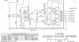
Hmmm, 355V on the screen! That's even exceeding the 6973's g2 rating.
"is the screen voltage normally kept lower than the plate?"
It's a good idea to do that for linearity and longevity, but many cost sensitive designs skipped the additional parts for a lower screen voltage supply. Using B+ for the screen supply also gets more power out of the tubes. First thing I would check though would be what the H__ pin 8 on the 6CZ5 is actually connected to inside the tube.
I've had similar problems, and while I've never tried to fix them, I have a few hunches as to what's wrong. First, the 6CZ5's different pin scheme leads to a higher input capacitance. I am also suspicious that it may have a different grid material than the 6973. Both of these can affect stability, and whether or not the tube will bias correctly in a given circuit.
The 6973 is quite happy with the 470k grid leak resistor, but I think the 6CZ5 would benefit from something smaller. Try 100k, and perhaps increase the coupling capacitor values to from 0.047uF to 0.22uF if it actually fixes the problem. Also consider adding a 1k grid-stopper resistor between the coupling cap and grid.
The 6973 is quite happy with the 470k grid leak resistor, but I think the 6CZ5 would benefit from something smaller. Try 100k, and perhaps increase the coupling capacitor values to from 0.047uF to 0.22uF if it actually fixes the problem. Also consider adding a 1k grid-stopper resistor between the coupling cap and grid.
I have tw pairs of Ampex 6973 monoblocs each running a pair of 6973. Problem is that those orignal RCA and Sylvania 6973s on the amps are running down to only 100 - 600 microhms in mutual conductance when I tested them; while if new, they should run 4800 microhms! Yuck! They do sound awefully dark and start to clip very early, making them quite unuseable.
Anyway, I have a pair of black plate RCA 6CZ5 at hand and they tested to about 65% of new mutual conductance, i.e. reading life left in them. While NOS 6973 sell for over 50 USD each, I decided it was time to use substitutes.
I have learnt some folks saying how to use 6CZ5.
http://www.audioasylum.com/audio/tubes/messages/5/51265.html
I summarize their suggestions:
1. connect pin 1 to pin 8;
2. reduce grid leak resistor from 470k ohm to 100k ohm;
3. strengthen the capacitor from 0.002 MF to 0.2 MF.
SO am I missing anything there?
Terence
I believe it is possible to build a very good amplifier with the 6CZ5 and this tube can be used to replace the 6973 in some circuits.
I found a 6CZ5 Sylvania Datasheet in this page of a very good Russian site :
Ðàäèîëàìïà 6CZ5
In the typical operation section, AF Power Amplifier for a class AB1 push-pull fixed bias circuit :
Plate voltage : 350V
Grid #2 voltage : 280V
Grid #1 voltage : -23.5V
Peak AF grid to grid voltage : 47V
Zero signal plate current : 46ma
Maximum signal plate current : 103ma
Zero signal grid #2 current : 3 ma
Maximum signal grid #2 current : 13ma
Load resistance plate to plate : 7500 ohms
Power output : 21.5 watts
Total harmonic distortion : 1% ...
Yes, 21.5 watts with only 1% THD, not only close to the 6973 in the same conditions but better if we can believe Sylvania ! My old RCA databook said 20 watts and 1.5% THD for the 6973, same supply voltages and load but -22V fixed bias, 58ma to 106ma plate current and 3.5ma to 14ma grid #2 current, almost the same.
The Sylvania datasheet maximum rating (center value) said for the plate in class A 350V and 12 watts dissipation, for the grid #2, 285V and 2 watts dissipation. Like TBL said, a maximum 100K grid leak resistance must be used with fixed bias but for cathode bias, 1 meg is OK. It is also a good idea to use a 1K grid blocking resistor like in most of the amplifier circuits. About the 12W maximum plate dissipation of the 6CZ5, the plate current for each tube at -23.5V bias is only 23ma, so 350V x 0,023 = 8.05 watts. This is well under the maximum and there is no risk toasting the plates if the fixed bias voltage is adjusted properly.
Of course, a bigger coupling capacitor must be used for fixed bias because the grid leak resistor is only 100K or less, 0.22uF is OK but 0.47uF or 1uF will give less bass attenuation. Many coupling capacitor can be used in parallel if necessary to get a higher capacitance, paper, mica and any film types are suitable but the best are paper in oil types, you can get some NOS from Russia or Ukraine for a very cheap price sometime on eBay or else ... Don't use ceramic for audio stage coupling and tantalum capacitors for cathode bypass, most connoisseur said they give bad results.
Happy new year and happy audio DIY !
I am much too late to said that but obviously, the schematic Bobby Dipole show cannot be used like that with 6CZ5, like smoking-amp said, 355V on the grid #2 is too high, according to Sylvania, the maximum is 285V ... Also, the grid leak resistors should be changed for 100K and the bypass capacitors for 0.22uF but the load of the 12AU7 will then be bigger and the amplifier response different. The fixed bias most also be adjusted for the new circuit.
But there is no mention of the primary plate to plate impedance of the output transformer and this is very important to know. Fortunately, it is very easy to find out what the transformer impedance ratio is by applying a high voltage to the primary (120V is OK) and measuring the voltage at the secondary without any load, assuming the right speaker impedance, usually 4, 8 or 15 ohms.
The impedance ratio is the square of the voltage ratio, this mean if you apply 120V on the primary ends where the plates are plugged and you get 3.92V at the 8 ohms tap on the secondary, the voltage ratio is 120/3.92 = 30.61:1 then the square of this ratio is 937:1 and 8 x 937 = 7496 ohms or just about 7500 ohms, perfect for a push-pull fixed bias amplifier using two 6CZ5 ... giving 21.5 watts with only 1% THD (according to Sylvania).
Notice something important about push-pull transformers, the impedance "view" by each output tube is only one fourth of the impedance plate to plate and not half because each tube use the half of the primary winding. In the case of a 7500 to 8 ohms transformer, the ratio of the voltage from half the primary winding to the secondary will be only 30.61/2 = 15.305:1, the square is 234.243:1 then the impedance ratio for each tube is about 234.243 x 8 = 1874 ohms ... one fourth of 7500 ohms ...
I explain that for novice tube amplifier designers, it is important to know for drawing correctly the AC load line and calculate the output power. Doing it for a single end amplifier is very easy but for a push-pull amplifier, it is much more complex. Another thing many people don't understand about load line is the operating point by which pass the load line, representing the position of the zero signal voltage and current, is the supply voltage less the DC drop in the output transformer primary. If the supply is 355V like in the schematic show by Bobby, and there is only 350V reaching the plate, that mean the drop in the winding is 5V, if the current is 23ma per tube, the DC resistance of half the winding should be about 5/0.023 = 217 ohms ...
Many will wonder how come the voltage between the cathode and plate of the tube can reach almost twice the supply voltage, at the lower end of the load line ? There is no magic, the ohm law said E=RI (voltage = resistance x current), in a tube amplifier, a small voltage variation on the grid produce a big current variation between the plate and the cathode. The peaks of this current vary from much under the operating point current to much lower, the impedance of the speaker is fixed at a medium frequency then is reflected impedance at the primary is also fixed. Like I said before, if the impedance for each tube is 1874 ohms and for example the maximum peak current reach 151ma alternatively for each tube, 1874 x 0.151 = 283V, then the peak to peak current is 302ma and the resulting peak to peak voltage is 566V. Because the supply voltage at the plate is 350V, the voltage between the plate and the cathode vary from 350 - 283 = 67V to 350 + 283 = 633V.
Those peak voltages and currents in each tube depend on the operating class and are just an example to illustrate what I try to explain and really apply only to class B because in class AB1 and AB2, both tube conduct part of the time and in class A all the time ...The formula to calculate the RMS output power is peak to peak voltage x peak to peak current / 8 or 0.302 x 566 / 8 = 21.4 watts RMS, this is the power you can reach with a class AB1 push-pull circuit using two 6CZ5, "less the power loss in the transformer" because the winding resistance and the magnetic loss ... The perfect transformer don't exist !
I hope this will help some new designers because it took me many years and Aspirin to understand how a output transformer is working, specially in a push-pull circuit, most electronic books are not really clear about that.
Why not just get some EH 6973s?? They are around $18.50 each (at least from me and some other vendors).
The 6CZ5 does fine as a 6973 sub unless the circuit runs the tubes right up at or above their spec limits. So it's quite possible that even real 6973s would have red plated in this case.
The 6CZ5 does fine as a 6973 sub unless the circuit runs the tubes right up at or above their spec limits. So it's quite possible that even real 6973s would have red plated in this case.
If they are brand new and tested, this is about the price they sold them on eBay, but the shipment is not included ...Why not just get some EH 6973s?? They are around $18.50 each (at least from me and some other vendors).
The 6CZ5 does fine as a 6973 sub unless the circuit runs the tubes right up at or above their spec limits. So it's quite possible that even real 6973s would have red plated in this case.
I see in Canadian dollars :
1 for 16.20$ + 12.69$ SH = 28.89$
2 matched for 33.46$ + 14.82$ SH = 48.28$ (24.14$ each)
3 matched for 50.19$ + 16.94$ SH = 67.13$ (22,38$ each)
4 matched for 66.92$ + 20.13$ SH = 87.05$ (21.77$ each)
The total price depend on the shipping cost.
I also see many NOS NIB and used/tested 6CZ5 for sale on eBay and it is hard to find some for less than 18$CAN (16.95$US) shipping included ... And they usually have only one or two for sale usually not matched. So you are right, it is better for this small difference to buy four brand new tested and matched Electro-Harmonix 6973 for 87.05$CAN (81.95$US) shipping included.
I conclude if you sale four brand new matched/tested EH 6973 for 74$US (78.62$CAN) and the shipping is over 7.94$US (8.43$CAN), the best price is on eBay ... 🙄
- Status
- Not open for further replies.
- Home
- Amplifiers
- Tubes / Valves
- 6973 VS 6CZ5 substitute