OK, thanks for that, much appreciated.
For the sake of searches, etc, I will do that in the future.
Rene
For the sake of searches, etc, I will do that in the future.
Rene
The more you shift to cl-B the more negative bias voltage.Makes the drive voltage higher too.And that is allready a bottle neck in designing the the positive side.
So i would say AB yes but not to much B.
Mona
So i would say AB yes but not to much B.
Mona
Yes of course, with those tubes and Class B, about 50V peak is needed each way, vs about 35 for AB. Duly noted. The challenge I think is more in going negative than going positive.
Keeping in mind that the top driver's plate resistor supply is taken from the plate of the bottom tube's plate, when the top tube's cathode is swinging positive, its driver's plate supply is being elevated volt for volt so keeping up is not a problem.
On the other hand, when the top tube is in its cutoff portion of the cycle, its cathode is being taken below ground by up to 200V. The other tube's plate is swinging down to 60V above ground, and the top driver still needs to be 50V below that. Only way is to return the cathode to a negative voltage of sufficient value. I'm estimating -150V but have not calculated things yet.
Thanks for the feedback.
Rene
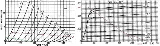
With just 260V supply I would bias the 6HJ5's at 70-80mA idle. With 110V on g2 it should be about -17 -to- -18V bias from Raytheon's datasheet. No need for class B. 40-50-60W output power is very little difference, very likely negligible, in listening mode.....
260V plate voltage, 110V g2, 75 mA it would have about 44W in a standard PP with 2.2K plate-to-plate load.
Let's try to get more practical 🙂
Keeping the power voltage low has the advantage that the driver section doesn't has to get into trouble and possible use of a power transfo for UPT.
I first tryed (only virtual 😉 ) a ECC81 ( forgot to take ou the gridstoppers, not needed any more) voltages looks to out of range but much gain.So, switch to a 6SN7 with a "design centre value" of 450volts on the plate with some positive feedback.
For the DC resistance i asumed 25 Ω (Rp).Anode dissipation of 16W is to much according to the data but the (allmost) same PL500 (or 504) is rated 16W.The transfo 2x115V to 18V is not exactely right but the closest "normal" obtainable.How about it ? ?
?
Mona
Keeping the power voltage low has the advantage that the driver section doesn't has to get into trouble and possible use of a power transfo for UPT.
I first tryed (only virtual 😉 ) a ECC81 ( forgot to take ou the gridstoppers, not needed any more) voltages looks to out of range but much gain.So, switch to a 6SN7 with a "design centre value" of 450volts on the plate with some positive feedback.
For the DC resistance i asumed 25 Ω (Rp).Anode dissipation of 16W is to much according to the data but the (allmost) same PL500 (or 504) is rated 16W.The transfo 2x115V to 18V is not exactely right but the closest "normal" obtainable.How about it ?
?Mona
Attachments

But the whole point of going this way is the gigantic advantage of not being hurt at all by leakage inductance (plate to plate, that is). And I don't subscribe to the idea that the driver has it all that hard. Unlike the case for the Mac, the upper tube is not being driven such that the drive voltage has to be both the gate swing plus the cathode swing, if that is what some of you may be thinking. Not at all. The driver's load resistor will see across it the normal +/- swing, whether it be 50v for Class B, or about 30v for AB.
While I am not going to categorically claim that this topology will result in a better amp than a standard P-P, in theory, it certainly can be. Perhaps bets can be hedged and I'll design the transformer so it can be switched from P-S if I don't like it, to standard P-P. That would mean no bifilar winding but, again, this topology is so flexible. The tight winding to winding coupling can be realized with a big ole cap and the windings effected in a common P-P configuration. Just have to make sure the windings are kept separate electrically so they, both primaries and secondaries, can be combined as needed per the configuration.
But my gut so far is telling that the P-S, or SEPP, will be just dandy. I have spent many years in my profession dealing with leakage inductance in high frequency inverters and leakage inductance in P-P topologies is not fun. Topologies in which leakage is less important, such as flyback and SEPIC converters, do make life so much easier. That is the way I view the SEPP. We'll see!
As far as power, I agree that there will be not much perceived loss if I cannot get the target 60W and instead wind up with around 50W or a bit less. 60W will remain the design target but I won't be obstinate about it. I will give up a few watts if needed for the sake of practicality and reliability. This includes biasing to other than B. While I am confident the leakage inductance dragon is very tame with the P-S/SEPP, there can still be some linearity issues around crossover which may not respond to NFB. We'll just have to see.
Thanks again,
Rene
Mona, that is a very intetesting bootstrap going on, very reminiscent of what was used in transistor amplifiers designs back in the 60s and 70s. Worth considering since it potentially minimizes or eliminates the need for the negative supply even with a differential driver.Just not sure it is properly referenced, I need to spend some quality time with this.
Your concern about I^2 R losses is real and I share it. Price to pay for going high current. My spreadsheet for my own design is predicting around 6-8 watts which still bothers me but is lower than the value that is bothering you.
So a tradeoff is that with higher current comes fewer turns since the load impedance is less than 400 Ohms for either primary winding. Allows for large wire and lower DCR, but of course losses are proportional to the square of the current while only linearly proportional to lowered resistance.
If it were easy, all would be doing it! 🙂
A new work project came in, that is the good news. It's also the bad news regarding this one. I hope to have time to crunch numbers and publish next week.
Rene
Ummm, 🙄
Those 115V windings are not going to handle much AC voltage swing at 30 Hz or 20 Hz. The driver is looking more reasonable I guess, with the low voltage B+. I don't think that is the real problem though. Just use a floating heater winding for the top tube.
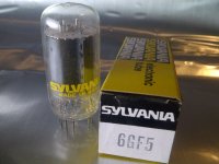
Try this 6GF5 tube out for driver duty, it's only $1 besides at ESRC Dollar Days. (770 V B+ rated) Tektronix used them in scopes. Everyone seems allergic to the 6GF5 because the data sheet doesn't have curves.
http://tubedata.milbert.com/sheets/201/6/6GF5.pdf
But, it's just a 6GE5, cut down to fit in a small bottle. (identical curve traces on a curve tracer)
A very well liked tube.
Curves:
http://tubedata.milbert.com/sheets/123/6/6GE5.pdf
The totem pole type amplifiers would solve many problems for DIY experimenters. So I applaud the development of one. (especially one with a single primary, which is SO flexible)
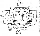
But all else failing (not likely), there is another approach that solves a similar set of design issues (without the heater problem). Uses an off the shelf (low Zpri) OT, provides 28% (for 40% UL taps) CFB, and does not require floating B+ supplies (un-like the Circlotron). The Elliptron (below): Both of these unusual approaches are sorely missing in DIY, and apparently equally feared. Such a great loss for DIY all these years.
🙄Those 115V windings are not going to handle much AC voltage swing at 30 Hz or 20 Hz. The driver is looking more reasonable I guess, with the low voltage B+. I don't think that is the real problem though. Just use a floating heater winding for the top tube.
Try this 6GF5 tube out for driver duty, it's only $1 besides at ESRC Dollar Days. (770 V B+ rated) Tektronix used them in scopes. Everyone seems allergic to the 6GF5 because the data sheet doesn't have curves.
http://tubedata.milbert.com/sheets/201/6/6GF5.pdf
But, it's just a 6GE5, cut down to fit in a small bottle. (identical curve traces on a curve tracer)
A very well liked tube.
Curves:
http://tubedata.milbert.com/sheets/123/6/6GE5.pdf
The totem pole type amplifiers would solve many problems for DIY experimenters. So I applaud the development of one. (especially one with a single primary, which is SO flexible)
But all else failing (not likely), there is another approach that solves a similar set of design issues (without the heater problem). Uses an off the shelf (low Zpri) OT, provides 28% (for 40% UL taps) CFB, and does not require floating B+ supplies (un-like the Circlotron). The Elliptron (below): Both of these unusual approaches are sorely missing in DIY, and apparently equally feared. Such a great loss for DIY all these years.
Attachments
Last edited:
The GF5 is just slimmer than the GE5. The height is the same. I really like the 6GE5 fat bottle!😀
Attachments
Last edited:
Some like them slim, and some like them fat. 🙂
You can get your choice with GF/GE, fit the same socket.
Then there is BIG and FAT:
You can get your choice with GF/GE, fit the same socket.
Then there is BIG and FAT:
Attachments
Last edited:
Some like them slim, and some like them fat. 🙂
You can get your choice with GF/GE
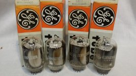
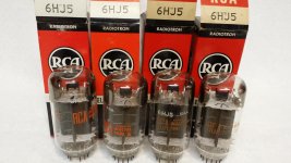
Slim (for their power rating) I have the 6HJ5 RCA.😉
Attachments
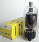
The 6DQ5, I know it very well. I used it for my first and only amp with sweep tubes. But it's gone now....to another home in good hands.Excellent tubes!
Put a plate cap on them and you get these:
The 6HF5s are the only tubes with caps I have. All other tubes, not just sweep tubes, are without. I will only make an exception if I can find some 35-40W sweep tubes.....
Last edited:
Ummm,
Those 115V windings are not going to handle much AC voltage swing at 30 Hz or 20 Hz.
Smoking Amp, not sure to what comment you refer here. If any of mine, at no time have I proposed using a power transformer in lieu of a proper audio output device. Just clarifying. I am saying that, with the low B+, all kinds of quality 1:2 transformers are available off the shelf for power supply duty. Rest assured that the very crucial output transformer will be done scientifically and correctly.
But all else failing (not likely), there is another approach that solves a similar set of design issues (without the heater problem). Uses an off the shelf (low Zpri) OT, provides 28% (for 40% UL taps) CFB, and does not require floating B+ supplies (un-like the Circlotron). The Elliptron (below): Both of these unusual approaches are sorely missing in DIY, and apparently equally feared. Such a great loss for DIY all these years.
I think you are right. IMHO, there are way too many opinions out there which are just that, opinions not very informed by scientific investigation and real curiosity but by very prevalent "guruship". According to some, one must use, for example, only paper wound oil filled caps or else the sound will suffer irrevocable damage. I have seen assertions that only old fashioned carbon comp resistors must be used or else. CC resistors have about the worst voltage coefficient of resistance out there and can cause a lot of problems, plus they are unstable over time and can be very noisy. On the other hand, if you need a resistor that will withstand horrible overloads and not burn to a crisp immediately, use a CC. A lot of rubbish out there. Perfectly good sweep tubes dismissed because they are not "audio", and so on. The result is stagnation and more building of replicas instead of investigation.
I only took a very quick look at the schematic posted by Smoking Amp on the Elliptron and need to spend a whole more in making sure I understand it. Off hand, it appears the topology tightly couples the plates to the cathodes in appropriate phase but it does not appear to do anything regarding plate to plate leakage inductance. Can you suggest or post a link which might contain a treatise on this approach?
The discussions we have been having regarding what I want to do have been mostly backed by technical concerns and we all have been going back and forth, with legitimate challenges and responses, etc. That is the way to do it.
So, Lord willing, given enough time, I do plan on completing a S-P or SEPP design and publishing full results, good bad or indifferent as they may be.
I am also going to look into all the types mentioned to see if anything is better than what I have chosen for the outputs. I am encouraged by the recent post (from 45, I think) regarding the 6DQ5 since I believe the 6H types to be derivatives. 45, can you post some amplifier performance figures, and tell us a bit more of the approach you used?
thanks to all,
Rene
I think smoking-amp was referring to Ketje's suggestion to use mains transformer for the OPT in post #87. Although Shoog seems to have success with them in some of his designs, I think he might have used even mains toroid's.
Hi Rene,
nothing special. It was a modified ultralinear as intented by Crowhurst. Just different partition of plate-cathode primary turns. It was 62.5%-37.5% in my case. As I said earlier the amp was designed for some nominal 8R speakers that weren't particularly difficult to drive but they did have some minimum impedance just over 4R (but almost purely resistive). So max Pout was obtained into 4R (just shy of 50W) with 300V plate voltage and 60 mA idle current and 2.5K plate-to-plate. Pout into 8R was about 30W and 32W into 2R!
After that experience I think that 75%-25% max partition in general is more than enough if high enough idle current class AB is used because it simplifies the driver stage quite a lot. It doesn't need plate resistor bootstrapping, too high voltage etc.
Actually if one settles for class A into nominal load 10-12% cathode fb should work very well. I will try this with the JA5's soon...
Oh, I see! This is the configuration you used to get low Zout with little overall NFB? So by using all this local FB ( G2) you created a low Z out amp, in addition to the lower impedance afforded by the 6DQ5. OK, I get it, thanks. Were you able to measure it's linearity in any way? If not with instruments, some sort of comparative subjective test?
I am not going to depart from the P-S thinking at this point, have not finished all the homework yet and it still appeals to me. In keeping with Smoking Amp's sentiments, I'll take this to some sort of conclusion.
For what it's worth, calculations I have done in the past as to the best G2 tapping for UL operation with sweep tubes have consistently come out in the 12-18% range. The much higher G2 gm over most other types of beam tubes is the reason. In my doodles, this allowed the potential for using literal taps on the transformer primary (instead of separate G2 windings) and zeners to stay within the G2 rating without the danger of cutting off the zeners, since the G2 DC is so much lower than for non sweep tubes.
Also one can seriously consider synthesizing the taps using MOSFETs which I would do if implementing a UL because of the flexibility in choosing the FB ratio via simple resistors.
Nevertheless, your experience proves the point that sweep tubes have much to offer and our community should embrace intelligent experimentation and leave pre conceived but unbased notions aside. Reach decisions using good engineering practice and not guruship.
Rene
No overall fb. I only use it when I have no other choice.
This was a rather quick build. I only evaluated Pout and FR with the scope. Also square waves. Very good. I was impressed with the sound.
G2 in the modified ultralinear is not connected to OT. It has its independent PSU. Possibly regulated. That's why it is very convenient with sweep tubes! It is called modified ultralinear because g2 is not referred to cathode. If you refer g2 directly to cathode then you have true pentode with cathode fb. At least this is my interpretation.
Last edited:
- Status
- Not open for further replies.
- Home
- Amplifiers
- Tubes / Valves
- 60W With Sweep Tubes, Different Topology