Hi @ all,
i´am new here - and my first question is
what do you thing about this power supply of my
Grundig Slimline Preamp from the 80´s.
The normal values are
C1 100µF / 100V modified to 1000µ
C2 22µF / 100V " to 33µ
C3 22µF / 100V " to 33µ + 100n
simulated the voltage ripple is gone from
30mV to 1mV @80mA @ 60VDC - it drives the preamp / tonecontrol / mc preamp and at last the speaker protection and relais control
there is still some noise - peak current measured is about 140mA on load
but i have no more area for bigger caps, because its very slim designed !
What´s the Solution ?
Attachments
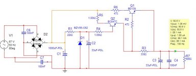
If you don't wanna change the (complete) design my recommendation would be to add a small cap (1nF...100nF) in parallel to D1 and C2 to cut-off more high frequency noise.
Next thing is about C6 and C7. Either you add two more caps between pins 1 & 2 and 1 & 3 of the bridge rectifier or you remove C6 and C7 and place a single cap between pins 2 and 3 of the rectifier. I've never seen such an 'asymmetrical' design before (I mean just one cap from either AC leg to GND only).
Furthermore you can check if the resistors are already metal-film types (they have usually a blue background color while carbon-film have an ochre background color). If they are carbon-films replace them with metal-film for further reduction of noise. However this woun't help for ripple voltages, just noise.
Talking about noise - standard zener diodes have anyway a larger noise floor than other reference elements. If you can avoid using standard Zeners it would make a difference too.
Thanks @ Corax
You are right, its really a asymmetrical design.
After the upper modifications the music sounds tightly
better in the middles.
In the next time, i change the resistors to metal-film and remove the caps around the bridge. 100nF / > 100V Wima types seems okay for C1 and the output cap. I think the Zener´s noise is a bit tricky, i try it with some values from 47n to 100n and measure, so wee see.
With best regards
ps...Here is the original schematic ...
An externally hosted image should be here but it was not working when we last tested it.
Another slightly ripple reduction scheme would be to divide R803 (22k in the origignal schematic - or R1 in your drawing) in to two equal parts (i.e. 2x 11k) and connect an additional cap from this new node (between the two new resistors) to ground. This will give you some sort of douple-pi-filter (C-R-C-R-C => C801 - R22a - Cnew - R22b - C802). The value of the new cap can be smaller than C802. These filter are more effective if the larger cap is at the end of the filter. In tube designs this is motre than welcome because the voltage drop to the end requires only 'low' voltage but high capacity caps at the end and high voltage low capacity caps at the beginning. This is a good argument for your wallet since large/big high voltage caps are so expensive. However, that means never let this filter bank run without a load or the caps at the end will have some sort of voltage 'stress' - but that's another story.  😀
😀
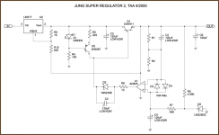
If you wanna go for a replacement of the 60V supply board with outstanding performance you might look for something called the "Jung Super Regulator". There's an articel series from Walter Jung called "Regulators for High-Performance Audio" (out of "The Audio Amateur", 1995) and if you're interested I would mail them to you.
😀 If you wanna go for a replacement of the 60V supply board with outstanding performance you might look for something called the "Jung Super Regulator". There's an articel series from Walter Jung called "Regulators for High-Performance Audio" (out of "The Audio Amateur", 1995) and if you're interested I would mail them to you.
Attachments
- Status
- Not open for further replies.