Hello all,
This is my DIY tube preamplifier, it's working and sounds great for years.
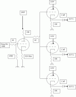
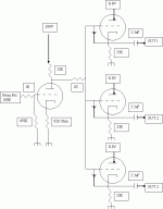
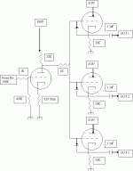
The first stage is classic grid drive, the output of this gain stage goes from it's anode through an 1Kohm resistor (direct, no capacitor) to the grid of the cathode follower (buffer).
I want to add two more buffers (three per channel total) to drive a six channel power amplifier so, each channel have it's own buffer.
Here is the schematic.
Will this work?
Kind regards
Padel
Attachments
What's the plate voltage of the first stage?
When direct coupling, it's a good idea to add a diode from grid to cathode of the CFs, reverse biased. This protects the tube during turn-on, but has no significant effect once things are warmed-up and operating.
When direct coupling, it's a good idea to add a diode from grid to cathode of the CFs, reverse biased. This protects the tube during turn-on, but has no significant effect once things are warmed-up and operating.
SY said:What's the plate voltage of the first stage?
When direct coupling, it's a good idea to add a diode from grid to cathode of the CFs, reverse biased. This protects the tube during turn-on, but has no significant effect once things are warmed-up and operating.
Thanks for the tip. I'll try it, allthough I have no ''blow up''problems with the current schematic.
Any comments about the schematic I posted?
Is this okey or I'm in ''dangerous''?
Regards
Padel
The location is fine. But reverse the diode orientation.
When the tube is first turn on, the diode allows the voltage from the first tube to follow into the 33k resistor. Once tube 2 turns on the path changes and diode does not play any role
CHeers
NIcholas
When the tube is first turn on, the diode allows the voltage from the first tube to follow into the 33k resistor. Once tube 2 turns on the path changes and diode does not play any role
CHeers
NIcholas
What's the plate voltage of the first stage? This is important to know to determine if the second stage (the CF) will operate properly.
NickC said:The location is fine. But reverse the diode orientation.
When the tube is first turn on, the diode allows the voltage from the first tube to follow into the 33k resistor. Once tube 2 turns on the path changes and diode does not play any role
CHeers
NIcholas
Yes, you are right, my mistake.
So, is this going to work or should I find a good helmet when power on for first time?

Padel
@Sy
I've simulated 188V on the first anode, 187V on the cathodes using Ritek's model. I haven't checked the accuracy of this model and right now I'm too tired to whip out the plate curves and a pencil. 😉
Cheers
Wayne :B
Edit:
P.S. And that exceeds the cathode/heater rating of 90V. 🙁
I've simulated 188V on the first anode, 187V on the cathodes using Ritek's model. I haven't checked the accuracy of this model and right now I'm too tired to whip out the plate curves and a pencil. 😉
Cheers
Wayne :B
Edit:
P.S. And that exceeds the cathode/heater rating of 90V. 🙁
Yeah, the CFs will have to be run off a separate heater supply biased up to 140-150V or so.
If your sim is accurate, the CFs at least have a decent (120V) potential across them. 6mA per section current draw, which is much too high for that tube- you'll be in the grid current region. Best to double the cathode resistors to drop the curent to 3 mA, maybe 69K.
Source impedance and drive capability will not be great since this is a low transconductance low current tube.
If your sim is accurate, the CFs at least have a decent (120V) potential across them. 6mA per section current draw, which is much too high for that tube- you'll be in the grid current region. Best to double the cathode resistors to drop the curent to 3 mA, maybe 69K.
53uA of grid current! There are other types better suited to this service. A 12AY7 is a high mu (44), low current, low microphonic, low noise tube used for low level amplification. Ya know a special kind of 12AX7 hehe 😀
And a 12AY7 being what it is you could get by with much lower B+. If you could get the plate voltage down, along with the current (higher plate and cathode resistors for the 1st stage) and use a higher cathode (CF) resistors, this will work. What I'm saying is that you are using resistor values more suited to a 6SN7...
Though "as is" it will amplify, but the distortion may be very high and not healthy for an 'AY7.
Cheers
Wayne 😉
SY said:Yeah, the CFs will have to be run off a separate heater supply biased up to 140-150V or so.
If your sim is accurate, the CFs at least have a decent (120V) potential across them. 6mA per section current draw, which is much too high for that tube- you'll be in the grid current region. Best to double the cathode resistors to drop the curent to 3 mA, maybe 69K.
Source impedance and drive capability will not be great since this is a low transconductance low current tube.
Hi all,
Thanks for your replies.
I just haved a look at Audio Note's M7 preamp schematic which is also using the 6072 tube at the line section, it is a direct coupled design too, without even a grid stop resistor.
M7 have 125K anode resistor, 5.6K cathode on the gain stage and 125K on the cathode of CF. Heaters supplies are biased at 100V.
Is this a better choise for multiple CF's?
Regards
Padel
- Status
- Not open for further replies.
- Home
- Amplifiers
- Tubes / Valves
- 6072 tube preamplifier.


