Hey Guys
I build this amp that I think is designed by "manojtm" by the name AUD600
I have problem delivering high power from it because as I increase the input signal the distortion begin to increase and the positive rail current consumption goes to 0 as the negative one draw way more power (about 1A)
So am I missing something here??
I appreciate any help from you guys
I'm not a pro and I really like to run this amp
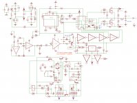
Here's the schematic that I'm using right now:
AUD600.Ver.01_02.jpg - Google Drive
Some Scope shots:
From pin 7 of IR2110 regarding to -75V Rail(V/Div=5 > Time/Div=2us > Probe on 10X)
1.jpg - Google Drive
From pin 1 of IR2110 regarding to -75V Rail(V/Div=5 > Time/Div=2us > Probe on 1X)
2.jpg - Google Drive
From pin 7 of IR2110 regarding to GND Rail(V/Div=5 > Time/Div=2us > Probe on 10X)
3.jpg - Google Drive
From pin 1 of IR2110 regarding to GND(V/Div=5 > Time/Div=2us > Probe on 10X)
4.jpg - Google Drive
From left side of output coil (2 mosfet outputs) regarding to GND(V/Div=5 > Time/Div=2us > Probe on 10X)
https://drive.google.com/file/d/139ZuaWKHnBZFf6X46KvbAAFc8a5auNX8/view?usp=sharing
I build this amp that I think is designed by "manojtm" by the name AUD600
I have problem delivering high power from it because as I increase the input signal the distortion begin to increase and the positive rail current consumption goes to 0 as the negative one draw way more power (about 1A)
So am I missing something here??
I appreciate any help from you guys
I'm not a pro and I really like to run this amp
Here's the schematic that I'm using right now:
AUD600.Ver.01_02.jpg - Google Drive
Some Scope shots:
From pin 7 of IR2110 regarding to -75V Rail(V/Div=5 > Time/Div=2us > Probe on 10X)
1.jpg - Google Drive
From pin 1 of IR2110 regarding to -75V Rail(V/Div=5 > Time/Div=2us > Probe on 1X)
2.jpg - Google Drive
From pin 7 of IR2110 regarding to GND Rail(V/Div=5 > Time/Div=2us > Probe on 10X)
3.jpg - Google Drive
From pin 1 of IR2110 regarding to GND(V/Div=5 > Time/Div=2us > Probe on 10X)
4.jpg - Google Drive
From left side of output coil (2 mosfet outputs) regarding to GND(V/Div=5 > Time/Div=2us > Probe on 10X)
https://drive.google.com/file/d/139ZuaWKHnBZFf6X46KvbAAFc8a5auNX8/view?usp=sharing
Hi
cant remember this circuit design is popular or work
go here APEX D200.2
Class D Amp with LM566, LM393 and 2XIRF530
working proof design from many DIYer, but take time to read and understand hidden secrets about class D
have finished PCB Class D amp today, because noboday can offer GERBER to produce pcb.
In todays time you can get for 5 USD PCB
Hi
cant remember this circuit design is popular or work
go here APEX D200.2
Class D Amp with LM566, LM393 and 2XIRF530
working proof design from many DIYer, but take time to read and understand hidden secrets about class D
have finished PCB Class D amp today, because noboday can offer GERBER to produce pcb.
In todays time you can get for 5 USD PCB
A few people report this schematic fully working including the designer at this thread:
https://www.diyaudio.com/forums/class-d/166214-ucd-25-watts-1200-watts-using-2-mosfets-266.html#post3202058
also be careful with schematics,
many Class D designs will work but important things not implemented,
to use amp can end in catastrophic failure.
proven working design is D4K5
YouTube
and APEX D200.2
In APEX schematic you need to add Load resistor 1.5 - 2.2 K 5W between output and GND
2 x Diode between output and +/- Rail
mail me for share xeperience
equal current just like negitive rail is drawing from power supply GND (positive rail is kind of center and it draws or deliver no current)
can somebody please explain this to me? is this normal?
can somebody please explain this to me? is this normal?
equal current just like negitive rail is drawing from power supply GND (positive rail is kind of center and it draws or deliver no current)
can somebody please explain this to me? is this normal?
Impossibile to explain in short,
this circuit is only for show how class D can work, not a final design
This is the Final Design from your circuit,
YouTube
if you not like build, buy TI TPAXXX Class D Chip amp
not loose time and money with Class D
study Apex D200 and crest CD3000 schematic to understand
Hi,
AUD600 amp is good you need to change 100k to 68k FB resistor and 10K/1W FB resistor to 2K2/2W and 56pF to 100pF/200v and 2N5401 emitter resistor 1K to 10K and IR2110 supply bootstrap cap 4.7uF to 22uF/63v and FSW adj. resistor 1k to 680 or 560 ohm
Regards
MANOJ
AUD600 amp is good you need to change 100k to 68k FB resistor and 10K/1W FB resistor to 2K2/2W and 56pF to 100pF/200v and 2N5401 emitter resistor 1K to 10K and IR2110 supply bootstrap cap 4.7uF to 22uF/63v and FSW adj. resistor 1k to 680 or 560 ohm
Regards
MANOJ
Hi,
AUD600 amp is good you need to change 100k to 68k FB resistor and 10K/1W FB resistor to 2K2/2W and 56pF to 100pF/200v and 2N5401 emitter resistor 1K to 10K and IR2110 supply bootstrap cap 4.7uF to 22uF/63v and FSW adj. resistor 1k to 680 or 560 ohm
Regards
MANOJ
Hi dear manojtm
I'm so glad to be able to get some help from the designer
I did fix the previous problem and now I have a working amp but now the problem is that I can not get more than 600W rms out of this amp on a 4 ohms load despite using a +-90 volts supply
(I get about 70 volts peak output and after that clipping start. at clipping point I have about +-84V on amp rails)
so why do you think this is happening?
I'm currently using IRF250M but I plan to change it to IRFP4227
With +-50V supply amp works great and I get output peak voltage near amplifier rail votages
Thank you again for this amp and your help and I appreciate it if you could help me fix my problem
I'm using ETD39 core with 1mm gap and 50 turns of 0.75mm wire
Is this good?
I also have etd49 in hand if necessary
can I use home made litz wire from 0.2mm wire instead of using 0.75mm wire to handle more current(skin effect)
Is this good?
I also have etd49 in hand if necessary
can I use home made litz wire from 0.2mm wire instead of using 0.75mm wire to handle more current(skin effect)
Hi,
Thanks
90v supply rail you will get more than 600W. you said you get 70v on output at 4R load. it means you get more than 1000W
for higher voltage you need to set FB resistor to get 29dB~32dB Max. gain
Regards
MANOJ
Thanks
now the problem is that I can not get more than 600W rms out of this amp on a 4 ohms load despite using a +-90 volts supply
(I get about 70 volts peak output and after that clipping start. at clipping point I have about +-84V on amp rails)
90v supply rail you will get more than 600W. you said you get 70v on output at 4R load. it means you get more than 1000W
for higher voltage you need to set FB resistor to get 29dB~32dB Max. gain
Regards
MANOJ
Can you post the pcb?
i'm still using manojtm pcb design V. 01(two seperate pcb)
you can find it here:
ucd 25 watts to 1200 watts using 2 mosfets
posted by Dear MANOJ
Hi,
Thanks
90v supply rail you will get more than 600W. you said you get 70v on output at 4R load. it means you get more than 1000W
for higher voltage you need to set FB resistor to get 29dB~32dB Max. gain
Regards
MANOJ
Hi dear MANOJ
I want to build two separate amp that each capable of delivering 800W rms @4 ohms load for my subwoofers
right now I get 70V peak output voltages that is about 50V rms that deliver about 625W rms @ 4 ohms
I know that for 800W @4ohms I only nead +-80 volts but to lower my SMPS output voltage I have to reduce 1 turn of each secondary winding that will cause to reduce the voltages below +-80 Volts
for higher voltage you need to set FB resistor to get 29dB~32dB Max. gain
Can you help me with that?
Hi,
for L use T157-2 core 1.5mm wire 49T (22uH)
High Volt(85v) use 47K (68K),56pF(100pF), 4K7/3W(2K2/3w) and add limiter circuit to avoid clip
Regards
MANOJ
for L use T157-2 core 1.5mm wire 49T (22uH)
High Volt(85v) use 47K (68K),56pF(100pF), 4K7/3W(2K2/3w) and add limiter circuit to avoid clip
Regards
MANOJ
Last edited:
Hi,
for L use T157-2 core 1.5mm wire 49T (22uH)
High Volt(85v) use 47K (68K),56pF(100pF), 4K7/3W(2K2/3w) and add limiter circuit to avoid clip
Regards
MANOJ
I don't have T157-2 at the moment and only etd 39 & etd49 & T106-2
I will buy it then if above core doesn't do the job
I don't know why but I get about 185KH frequency with 1K resistor and 135KH with 560 ohms resistor
with 1k resistor:
IMG_20190531_132441.jpg - Google Drive
with 560 ohms:
IMG_20190531_132213.jpg - Google Drive
Time/Div is set to 2us
Ps: the measurements is from before the L(mosfets output) and GND
with 1k resistor:
IMG_20190531_132441.jpg - Google Drive
with 560 ohms:
IMG_20190531_132213.jpg - Google Drive
Time/Div is set to 2us
Ps: the measurements is from before the L(mosfets output) and GND
- Status
- Not open for further replies.
- Home
- Amplifiers
- Class D
- 600W Class D amp