Heeelp!
Don't ask me why—it's a very long story—but I need a working Yamaha A760 amplifier. So far I've bought 3, and spent a fortune on refurb jobs by local techs that work on vintage gear. One of these techs has now passed away, and I want to avoid bringing things back to the other two shops because they've kept machines for over a year before!
I currently have one that works perfectly except for one thing: there's a hum/buzz on the speakers whenever any line level RCA input/output is plugged in to the machine.
I'm in North America, and the fundamental frequency of the hum seems to be 60Hz, with higher frequency noise harmonics, so this seems to be an AC grounding issue between the amp and other components. The noise is relatively quiet and stays the same volume regardless of where the volume control's at, but it seems to cause slight distortion in the audio signal.
When everything is unplugged from the line level input board, the hum disappears. There's no hum if just the speakers, turntable RCAs (and turntable ground wire) are connected. There is also no hum if the device plugged into the line level RCA board is not running on AC, like if it's an iPod running on battery. The RCA cables I have are decently shielded, and there is no hum problem on my other A760 amplifiers when I plug the same devices/cables in. (Those amps just have other problems I can't fix.)
While working on a prior A760 of mine with no hum issue, one tech told me there was a grounding problem with the chassis and he soldered a wire between the ground rail of the RCA inputs, the input switches and the chassis to correct it. So I used a multimeter to test continuity and resistance between the RCA ground and the chassis on this current unit. I assumed there may be oxidation in the chassis or a failing solder joint somewhere on a circuit board but there's good continuity for all RCA plugs to the chassis.
So I put this out to the community...what else could be going on here? Is there a specific component that may have begun to fail, and how can I test for that myself with a multimeter?
A few components have already been replaced, but I don't think the power supply in it has been touched. I know these machines have a weird "X" power supply, so maybe something's gone bad in that.
I tried testing the grounding of the two pairs of filter capacitors but finding the negative pin became confusing as they seem to be wired in series on the board and I'm not sure about discharging them etc.
(It may sound like I know what I'm doing but I've just done a lot of googling. I'm new to using a multimeter and not great at soldering so very simple instructions without abbreviated techy words would be best!)
Well, let's start chipping away at it. Divide and conquer is the best route, if not try a bunch of systematic experiments until you figure something out!
Non AC powered sources (iPod) have no noise, so I don't think there is anything at all wrong with the amplifier.
I see in the photo from the Yamaha website, this has an IEC (computer cord) style plug for the line cord, but in the photo it shows only two terminals and no ground lug- is yours that way, or does it actually have 3 terminals?
Either way, the first thing I suspect is that your sources may be on a different AC circuit than the amp- is this possible? Could you describe your power distribution for the system? Is it all plugged into the same power strip, or different outlets? Is one outlet possibly switched at the wall (like for a lighting circuit)?
Are your plugs there polarized? Can you turn one around to switch polarity between amp and source? I would try one single AC powered source that is making the noise- If you move this one source from input to input to input, is the result always the same? If you disconnect your turntable and ground lead, do the other sources still make noise?
Heeelp!
Don't ask me why—it's a very long story—but I need a working Yamaha A760 amplifier. So far I've bought 3, and spent a fortune on refurb jobs by local techs that work on vintage gear. One of these techs has now passed away, and I want to avoid bringing things back to the other two shops because they've kept machines for over a year before!
There's certainly one easy answer to your dilemma ... pay for some psychological help to remove your need for a Yamaha A760! Then buy something modern. 😀
I currently have one that works perfectly except for one thing: there's a hum/buzz on the speakers whenever any line level RCA input/output is plugged in to the machine.
I'm in North America, and the fundamental frequency of the hum seems to be 60Hz, with higher frequency noise harmonics, so this seems to be an AC grounding issue between the amp and other components. The noise is relatively quiet and stays the same volume regardless of where the volume control's at, but it seems to cause slight distortion in the audio signal.
When everything is unplugged from the line level input board, the hum disappears. There's no hum if just the speakers, turntable RCAs (and turntable ground wire) are connected. There is also no hum if the device plugged into the line level RCA board is not running on AC, like if it's an iPod running on battery. The RCA cables I have are decently shielded, and there is no hum problem on my other A760 amplifiers when I plug the same devices/cables in. (Those amps just have other problems I can't fix.)
I am not familiar with old Japanese integrateds but I did experience a mains buzz from the spkrs once, many years ago, when I introduced a Chinese tube amp into my system.
The problem seemed to be that this amp didn't have its RCA input sockets isolated from its chassis ... so I was experiencing a ground loop.
Are the RCA sockets in a Yamaha A760 amplifier isolated from the metal chassis?
I note you did say this "there's good continuity for all RCA plugs to the chassis" - which would suggest that they aren't isolated?
Ok, sorry- I see what I did- I was looking at a picture for the "RX-A760". The correct one is shown below correct?
A fellow likes what a fellow likes. Not nearly as vintage as many of the fine amplifiers you see here, it looks really good to me, and just because something is "modern" does not at all mean it's better.
There are a lot of misunderstandings in this area. I think "ground loop" is a bit of a misnomer- I prefer "ground bounce". AC/DC currents flowing through conductors will cause a voltage drop across the resistance of the conductor. Ever sit on a trampoline when a big kid is bouncing furiously on it? This is what inputs experience when the drivers and speakers are pounding on the ground conductor- The so-called ground is not ground everywhere- but at different AC/DC voltage potential at different places because the currents flowing causing these voltage drops through the ground conductor. In vacuum tube chassis, a thick smallish box, the entire chassis is used as the center of the star in the star ground. The chassis itself is like a million ground wires, connecting every place to every other place with a low enough resistance there is not appreciable voltage drop, such that you can solder a ground to just about anywhere on the chassis and you are good. Even in this scenario the ground of the power transformer secondary is tied to the chassis very closely or at the same point as the speaker return ground, to minimize voltage drop. In most vacuum tube amps the input connectors are soldered right to the chassis, and there is not a problem because there is not enough drop across the structure of the chassis.
In the larger more complicated metal structure of modern amps, stamped out of paper thin sheet metal, with multiple PCB's all connected via harnesses, there is much more opportunity for ground currents to induce voltage drops across the chassis, so inputs may or may not be tied directly to the chassis, but both the inputs and chassis need to be at ground potential. You should measure near zero resistance between the input grounds and chassis grounds. A grounding strategy will have been adopted by the design engineer to make sure there are no problems with ground bounce. Typically more of a star ground is chosen and the chassis is not relied upon.
The design of this particular amplifier looks good. I'm sure the designer addressed any issues here. The fact that an independently powered source is not causing this noise is proof of that. I think the problem here is that one of the sources is a bad actor not playing well with the others. Perhaps it's the turntable because of it's direct ground connection- OP will need to experiment with different combinations of sources and figure out which one is not playing nice with the others.

There's certainly one easy answer to your dilemma ... pay for some psychological help to remove your need for a Yamaha A760! Then buy something modern.
A fellow likes what a fellow likes. Not nearly as vintage as many of the fine amplifiers you see here, it looks really good to me, and just because something is "modern" does not at all mean it's better.
The problem seemed to be that this amp didn't have its RCA input sockets isolated from its chassis ... so I was experiencing a ground loop.
There are a lot of misunderstandings in this area. I think "ground loop" is a bit of a misnomer- I prefer "ground bounce". AC/DC currents flowing through conductors will cause a voltage drop across the resistance of the conductor. Ever sit on a trampoline when a big kid is bouncing furiously on it? This is what inputs experience when the drivers and speakers are pounding on the ground conductor- The so-called ground is not ground everywhere- but at different AC/DC voltage potential at different places because the currents flowing causing these voltage drops through the ground conductor. In vacuum tube chassis, a thick smallish box, the entire chassis is used as the center of the star in the star ground. The chassis itself is like a million ground wires, connecting every place to every other place with a low enough resistance there is not appreciable voltage drop, such that you can solder a ground to just about anywhere on the chassis and you are good. Even in this scenario the ground of the power transformer secondary is tied to the chassis very closely or at the same point as the speaker return ground, to minimize voltage drop. In most vacuum tube amps the input connectors are soldered right to the chassis, and there is not a problem because there is not enough drop across the structure of the chassis.
In the larger more complicated metal structure of modern amps, stamped out of paper thin sheet metal, with multiple PCB's all connected via harnesses, there is much more opportunity for ground currents to induce voltage drops across the chassis, so inputs may or may not be tied directly to the chassis, but both the inputs and chassis need to be at ground potential. You should measure near zero resistance between the input grounds and chassis grounds. A grounding strategy will have been adopted by the design engineer to make sure there are no problems with ground bounce. Typically more of a star ground is chosen and the chassis is not relied upon.
The design of this particular amplifier looks good. I'm sure the designer addressed any issues here. The fact that an independently powered source is not causing this noise is proof of that. I think the problem here is that one of the sources is a bad actor not playing well with the others. Perhaps it's the turntable because of it's direct ground connection- OP will need to experiment with different combinations of sources and figure out which one is not playing nice with the others.
Last edited:
Thanks guys! Answering follow-up questions from both of you below:
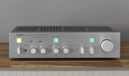
Yes, that's the back panel of the correct amp in the pic. Attaching a pic of the front panel here.
The amp's AC cable is non-polarized 2-prong, and flipping the plug in the socket causes no improvement to the hum/buzz.
The line level sources I'm connecting to the RCA inputs/outputs all have 3-prong AC cables.
These sources are connected to the same power bar (and therefore same AC wall socket & circuit). The wall socket isn't switched at the wall.
Key thing: if I swap in any other (same model) amplifier in the setup, connecting these same sources, there's no hum/buzz.
Connecting my 2-prong turntable with grounding wire (and/or speakers) to the amp causes no hum/buzz. It's just AC-powered devices into the line-level RCA board.
With the turntable RCAs, turntable ground wire and speakers disconnected, the hum/buzz is still audible on headphones (again, only when one of the AC-powered sources is connected to any of the line level inputs/outputs).
Re: isolation from the chassis...from my googling, my understanding is that because the amp is a 2-prong device, it can't have be "True Chassis Grounding" design where it would be grounded to earth via the AC cable. And I don't think it's a "Class II Double-Insulated Device" design because it would have visible layers of insulating materials inside it. So it should be a "Floating Ground Design, where the chassis is isolated from the electrical ground to prevent ground loops and reduce noise."
And my understanding from there is that the "signal ground" (ie the negative sleeve of the RCA cables) should be connected to the chassis, and when I use my multimeter to test continuity between any of the line-level RCA sleeves and various points on the chassis, it's solid. (Also, there was continuity between the turntable grounding screw and the chassis, the input switches and the chassis, and the negative pin of 2 of the 4 main filter capacitors and the chassis...I'm confused about what this means re: the other two filter capacitors. They appear to be connected in series on the circuit board, but googling gives me explanations that they're "not truly wired in series". And the negative pins of two do not have continuity with the chassis.)
Also attaching a pic of the internal mod the (no longer living) tech did on one of my other machines. He's ensured the ground rail of the line level RCA board is connected to the input switch casings and the chassis via the thick purple wire he's soldered in. *This is one of my A-760II amps, and there are some differences between the Mark I and Mark II, but the design of the grounding should apply. With that amp, as I mentioned, there was no hum before he did the mod or after, but he mentioned that when he did his routine testing he found that there was a grounding problem and fixed it.

So I guess first things first, is my understanding about all the above right? The amp is Floating Chassis Design, there's an AC circuit and an audio signal circuit, the audio signal should be making contact with the chassis but the chassis would not be making any direct contact with the AC circuit?
Could the hum/buzz be the result of the audio circuit accidentally making direct contact/getting leakage from the amp's internal AC circuit? (I feel like that would be dangerous, but apparently it can just cause this type of hum/buzz?)
The other possibility I'm intuiting is a component in the power supply (maybe a capacitor) or one of the filter caps on the main board may be failing and that could cause failing isolation of the two circuits (ie interference) of some kind? I believe the techs would have tested the filter caps, but I don't think they took the power supply apart.
Thanks again!
Yes, that's the back panel of the correct amp in the pic. Attaching a pic of the front panel here.
The amp's AC cable is non-polarized 2-prong, and flipping the plug in the socket causes no improvement to the hum/buzz.
The line level sources I'm connecting to the RCA inputs/outputs all have 3-prong AC cables.
These sources are connected to the same power bar (and therefore same AC wall socket & circuit). The wall socket isn't switched at the wall.
Key thing: if I swap in any other (same model) amplifier in the setup, connecting these same sources, there's no hum/buzz.
Connecting my 2-prong turntable with grounding wire (and/or speakers) to the amp causes no hum/buzz. It's just AC-powered devices into the line-level RCA board.
With the turntable RCAs, turntable ground wire and speakers disconnected, the hum/buzz is still audible on headphones (again, only when one of the AC-powered sources is connected to any of the line level inputs/outputs).
Re: isolation from the chassis...from my googling, my understanding is that because the amp is a 2-prong device, it can't have be "True Chassis Grounding" design where it would be grounded to earth via the AC cable. And I don't think it's a "Class II Double-Insulated Device" design because it would have visible layers of insulating materials inside it. So it should be a "Floating Ground Design, where the chassis is isolated from the electrical ground to prevent ground loops and reduce noise."
And my understanding from there is that the "signal ground" (ie the negative sleeve of the RCA cables) should be connected to the chassis, and when I use my multimeter to test continuity between any of the line-level RCA sleeves and various points on the chassis, it's solid. (Also, there was continuity between the turntable grounding screw and the chassis, the input switches and the chassis, and the negative pin of 2 of the 4 main filter capacitors and the chassis...I'm confused about what this means re: the other two filter capacitors. They appear to be connected in series on the circuit board, but googling gives me explanations that they're "not truly wired in series". And the negative pins of two do not have continuity with the chassis.)
Also attaching a pic of the internal mod the (no longer living) tech did on one of my other machines. He's ensured the ground rail of the line level RCA board is connected to the input switch casings and the chassis via the thick purple wire he's soldered in. *This is one of my A-760II amps, and there are some differences between the Mark I and Mark II, but the design of the grounding should apply. With that amp, as I mentioned, there was no hum before he did the mod or after, but he mentioned that when he did his routine testing he found that there was a grounding problem and fixed it.
So I guess first things first, is my understanding about all the above right? The amp is Floating Chassis Design, there's an AC circuit and an audio signal circuit, the audio signal should be making contact with the chassis but the chassis would not be making any direct contact with the AC circuit?
Could the hum/buzz be the result of the audio circuit accidentally making direct contact/getting leakage from the amp's internal AC circuit? (I feel like that would be dangerous, but apparently it can just cause this type of hum/buzz?)
The other possibility I'm intuiting is a component in the power supply (maybe a capacitor) or one of the filter caps on the main board may be failing and that could cause failing isolation of the two circuits (ie interference) of some kind? I believe the techs would have tested the filter caps, but I don't think they took the power supply apart.
Thanks again!
Attachments
Inside, if you already ruled out the cable.
You could measure the continuity between rca ground at the socket and the chassis. Usually they should have very low resistance between them.
You could measure the continuity between rca ground at the socket and the chassis. Usually they should have very low resistance between them.
Ah, yes, as explained in the first post, I tested continuity/resistance between the RCA ground and the chassis. Solid continuity, zero resistance. But still, a hum...
Ok- lots to dig into.
This is again confirmed with the statement:
Yes, this is a floating ground design. The transformer provides complete isolation from the AC circuit (and earth ground), and this should be true of all of the sources as well, so the shield of the RCA cables can easily bring all source and amplifier signal grounds to the same potential so no current flows through the shield. Yes, signal ground is definitely different than earth ground, but they generally need to be kept close to each other, but usually through a resistor or capacitor, and only in one carefully chosen place.
After crawling around through the absolutely horrible schematics (for the original version?) found here:
https://audiocircuit.dk/downloads/yamaha/Yamaha-A760-int-sm.pdf
In the "function" board where all of the RCA inputs are received, the ground sleeve of each of the inputs are brought to a common ground on the function board, but this ground is not meant to be tied to the chassis here- the schematic shows this board ground connected to the chassis only through two 0.033uF caps, which would be to shunt RF frequencies to chassis ground, but are an "open" for DC or audible frequencies. The only place this function board ground is shown connecting anywhere is through the shield wrapped around the selected "input" signal that leaves the function board going to the "tone control 2" and "tone control 3" boards where the volume control and main direct switch is.
I'm afraid the technician made an incorrect repair with the purple wire. I'm sorry to say, this was a lazy move. This created a ground loop inside of the amplifier at this point. He probably took the simplistic view that ground is ground, and tied it together. The correct repair would have been to find out where the flaky grounding problem was occurring and repair that rather than modifying the design. One could pull the function board, and check/resolder the ground connections of the RCA inputs and switches, where breaks in the solder can commonly occur due to thermal and mechanical stress. The ground shield is also treated like a signal, in that it passes through the main/direct switch. One of these switches could be corroded or worn, and causing a flaky ground he observed.
I would suggest clipping the purple wire between the RCA ground sleeve and the chassis sheet metal. This will be easy to reconnect later should you choose. I would also hit the main/direct switch with some electrical cleaner and work it pretty well, and see where you are at there. If there is indeed a flaky ground at that point, perhaps try flexing the function/input board and see if you hear noises in the audio or hum coming and going. Worse case scenario you can always reconnect the purple wire and you have lost no ground. (pardon the pun)
I think that is the most important thing that has been said. It's the amp. That is the magic of divide and conquer.Key thing: if I swap in any other (same model) amplifier in the setup, connecting these same sources, there's no hum/buzz.
This is again confirmed with the statement:
It's the amp.With the turntable RCAs, turntable ground wire and speakers disconnected, the hum/buzz is still audible on headphones (again, only when one of the AC-powered sources is connected to any of the line level inputs/outputs).
Yes, this is a floating ground design. The transformer provides complete isolation from the AC circuit (and earth ground), and this should be true of all of the sources as well, so the shield of the RCA cables can easily bring all source and amplifier signal grounds to the same potential so no current flows through the shield. Yes, signal ground is definitely different than earth ground, but they generally need to be kept close to each other, but usually through a resistor or capacitor, and only in one carefully chosen place.
After crawling around through the absolutely horrible schematics (for the original version?) found here:
https://audiocircuit.dk/downloads/yamaha/Yamaha-A760-int-sm.pdf
In the "function" board where all of the RCA inputs are received, the ground sleeve of each of the inputs are brought to a common ground on the function board, but this ground is not meant to be tied to the chassis here- the schematic shows this board ground connected to the chassis only through two 0.033uF caps, which would be to shunt RF frequencies to chassis ground, but are an "open" for DC or audible frequencies. The only place this function board ground is shown connecting anywhere is through the shield wrapped around the selected "input" signal that leaves the function board going to the "tone control 2" and "tone control 3" boards where the volume control and main direct switch is.
I'm afraid the technician made an incorrect repair with the purple wire. I'm sorry to say, this was a lazy move. This created a ground loop inside of the amplifier at this point. He probably took the simplistic view that ground is ground, and tied it together. The correct repair would have been to find out where the flaky grounding problem was occurring and repair that rather than modifying the design. One could pull the function board, and check/resolder the ground connections of the RCA inputs and switches, where breaks in the solder can commonly occur due to thermal and mechanical stress. The ground shield is also treated like a signal, in that it passes through the main/direct switch. One of these switches could be corroded or worn, and causing a flaky ground he observed.
I would suggest clipping the purple wire between the RCA ground sleeve and the chassis sheet metal. This will be easy to reconnect later should you choose. I would also hit the main/direct switch with some electrical cleaner and work it pretty well, and see where you are at there. If there is indeed a flaky ground at that point, perhaps try flexing the function/input board and see if you hear noises in the audio or hum coming and going. Worse case scenario you can always reconnect the purple wire and you have lost no ground. (pardon the pun)

Thanks jxd, I'll start there!Then, find the ground trace on the PCB and test the continuity against the rca ground.
Do you happen to have your television or cable box hooked up to your system? If so, disconnect it from your audio system and see if that helps.I'm in North America, and the fundamental frequency of the hum seems to be 60Hz
For context, I get hum over the coax cable coming from my cable television provider. A power strip with a built-in coax filter that solved the issue for me.
Thanks for going into that horrific schematic—being really inexperienced with this stuff I couldn't read it clearly enough to make sense of it. I think I understand most of your explanation, and I'll pull the function board to check it, plus test/clean the Main Direct switch. Should I also test the two 0.033uF caps between the Function board and the chassis? (To do this I put the multimeter probes on the pins, in which mode, DC voltage? Do I discharge them first somehow?)Ok- lots to dig into.
I think that is the most important thing that has been said. It's the amp. That is the magic of divide and conquer.
This is again confirmed with the statement:
It's the amp.
Yes, this is a floating ground design. The transformer provides complete isolation from the AC circuit (and earth ground), and this should be true of all of the sources as well, so the shield of the RCA cables can easily bring all source and amplifier signal grounds to the same potential so no current flows through the shield. Yes, signal ground is definitely different than earth ground, but they generally need to be kept close to each other, but usually through a resistor or capacitor, and only in one carefully chosen place.
After crawling around through the absolutely horrible schematics (for the original version?) found here:
https://audiocircuit.dk/downloads/yamaha/Yamaha-A760-int-sm.pdf
In the "function" board where all of the RCA inputs are received, the ground sleeve of each of the inputs are brought to a common ground on the function board, but this ground is not meant to be tied to the chassis here- the schematic shows this board ground connected to the chassis only through two 0.033uF caps, which would be to shunt RF frequencies to chassis ground, but are an "open" for DC or audible frequencies. The only place this function board ground is shown connecting anywhere is through the shield wrapped around the selected "input" signal that leaves the function board going to the "tone control 2" and "tone control 3" boards where the volume control and main direct switch is.
I'm afraid the technician made an incorrect repair with the purple wire. I'm sorry to say, this was a lazy move. This created a ground loop inside of the amplifier at this point. He probably took the simplistic view that ground is ground, and tied it together. The correct repair would have been to find out where the flaky grounding problem was occurring and repair that rather than modifying the design. One could pull the function board, and check/resolder the ground connections of the RCA inputs and switches, where breaks in the solder can commonly occur due to thermal and mechanical stress. The ground shield is also treated like a signal, in that it passes through the main/direct switch. One of these switches could be corroded or worn, and causing a flaky ground he observed.
I would suggest clipping the purple wire between the RCA ground sleeve and the chassis sheet metal. This will be easy to reconnect later should you choose. I would also hit the main/direct switch with some electrical cleaner and work it pretty well, and see where you are at there. If there is indeed a flaky ground at that point, perhaps try flexing the function/input board and see if you hear noises in the audio or hum coming and going. Worse case scenario you can always reconnect the purple wire and you have lost no ground. (pardon the pun)
Also, good pun! To be clear, though, the image with the purple wire mod is my previous unit, not the one with the hum. Backing up here, I've owned 3 of these amps over the last 15 years:
Unit #1 did not have a hum issue. It had burnt out bulbs. The tech I brought it to (who is no longer living) replaced them with LEDs, and said he found a grounding issue in the process but fixed it with that purple wire. This unit worked for years but eventually had other sound problems and I cannibalized it to fix issues with Unit #2.
Unit #2 also worked for years but had similar sound issues to Unit #1, turns out there's a common problem with speaker relays needing to be replaced.
Unit #3 is the one I'm asking about here. It's had its speaker relay replaced and the one remaining problem is this hum/buzz. It seems like the easiest one for me to get working here. I remembered the grounding mod done by the tech on Unit #1, so opened up that machine and realized it involved the RCA inputs, so, guided by other internet instructions, I rigged up a temporary grounding wire with the same components. But no change in the hum, so here we are.
Update...I just tried connecting some 2-prong line-level sources to the RCA jacks. No hum/buzz. So it's just when I connect 3-prong devices. Maybe that narrows down where the problem might lie?
Since your amplifier has only a 2 prong plug, there is no way the signal ground can be connected to earth ground, so signal ground should be completely floating. It could perhaps be connected to neutral through a capacitor which is why I asked about flipping plugs. Is the plug on this amplifier polarized? When you connect a source that has a 3-prong plug and get the hum, if you reverse the power plug for the amplifier is the hum still there?
Another experiment might be to defeat the earth ground lug of the source causing the hum- Those of us that grew up in old houses from the 1950's had home wiring that did not include a ground connector, so outlets only had two slots, and we had to use adapters like that below to connect a modern 3-prong plug to the outlet. Since it is not advised or worthwhile clipping off the ground prong on the offending source power cable, if you used an adapter like that shown below to disconnect the source from earth ground, does the hum go away?

Another experiment might be to defeat the earth ground lug of the source causing the hum- Those of us that grew up in old houses from the 1950's had home wiring that did not include a ground connector, so outlets only had two slots, and we had to use adapters like that below to connect a modern 3-prong plug to the outlet. Since it is not advised or worthwhile clipping off the ground prong on the offending source power cable, if you used an adapter like that shown below to disconnect the source from earth ground, does the hum go away?
Reversing the power plug for the amplifier causes no change to the hum when a source with a 3-prong plug is connected. I'll get one of these adaptors for the 3-prong sources and try it out, but I assume it would not be advisable to use the setup, longterm, that way?
Won't really matter. Sorry to sound like a Luddite, but back in the day =everything= was only 2 prong and we survived just fine.
Then the lawyers came in . . .)
The fantasy behind grounding through the cord is that if there were a catastrophic failure inside the appliance and the inside of the cabinet were to come into contact with AC voltage, the ground prong connected to the cabinet would shunt the current to ground and protect you. In my experience there is so much equipment that runs on only 2-prong cords, so many caps connecting chassis to neutral (that becomes cap to hot if you reverse the plug), and so many inputs/outputs/signals and voltages we can expose ourselves to, that having an earth grounded component in the mix gives you a ready thing to shock yourself on when YOU become the circuit between something hot and the grounded cabinet. In a perfect world everything would be floating or double insulated in my opinion. (Don't sue me 😉 )
One thing I have learned these years is not to “upgrade” old amp from 2-prong cable with 3-prong cable.
Amp, usually comes with a ground binding screw that allow you to bind the amp and the source together. If that solve the issue, that means your RCA ground is broken somewhere.
Amp, usually comes with a ground binding screw that allow you to bind the amp and the source together. If that solve the issue, that means your RCA ground is broken somewhere.
By this do you mean the same ground terminal on the back of the amp used for the turntable? Or a screw inside the amp? And that gets attached to the chassis of the source?Amp, usually comes with a ground binding screw that allow you to bind the amp and the source together. If that solve the issue, that means your RCA ground is broken somewhere.
- Home
- Amplifiers
- Solid State
- 60 Hz Hum/Buzz Only When RCA Inputs Connected - Yamaha A760