Thanks for the input. I do not doubt their reliability but more of the compromise. It is one or the other "evil". I will try to explain:
With AC we could expect hum and if not regulated even drift (not so when regulated and on high frequency), the other is indeed the field shift. When isolating the heater all is fine but unfortunately the heater is our cathode and interacts with the grid which is very close to the heater. Now imagine that one side is on -2.5V (with center tap) and the other is +2.5 (for a 300B tube) then the bias setting against the grid is on one side higher then on the other and current is unequally drawn. This might not be a problem of the reliability of the amp but will (in my opinion) compromise the performance of the tube.
With AC we could expect hum and if not regulated even drift (not so when regulated and on high frequency), the other is indeed the field shift. When isolating the heater all is fine but unfortunately the heater is our cathode and interacts with the grid which is very close to the heater. Now imagine that one side is on -2.5V (with center tap) and the other is +2.5 (for a 300B tube) then the bias setting against the grid is on one side higher then on the other and current is unequally drawn. This might not be a problem of the reliability of the amp but will (in my opinion) compromise the performance of the tube.
The two ends of the filament have a different potential towards ground. So you can't just switch your bias resistor from one node to the other without changing bias.
That's about it.
That's about it.
Last edited:
With DC however there is always a field shift, don't you agree?
That might actually be a benefit. If only part of the plate and grid areas are used the tube might behave more linearly. This depends on the construction and needs some trial and testing. In any case it will be not worse in terms of performance.
With AC heating you surely get more distortion (intermodulation).
If the tube should get too hot as that guy fears then the rating of their tubes is exaggerated or there is a design flaw. It's not a problem in general.
Actually for ALL the NOS battery DHT's and DHP's DC supply was and is recommended. For some it is the only way!
I do not think that only a part of the grid area is used as the grid does not care but the current drawn from the heater wire is drawn more or less on different areas. Therefore i can imagine that the tube life will be less in this case (maybe reversing the voltage sometimes could prolong tube life).
Intermodulation distortion is possible , true. That is why i stated that all option have their advantage and disadvantage (It is one or the other "evil").
DHT battery tubes are not to be compared as these never have been designed to work in high fidelity equipment (more for portable radio and military where durability and low power consumption is more important then distortion numbers). We know now that these can perform greatly in a good designed amp.
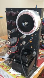
"For some it is the only way!" Did they ever tried high frequency (resonant) power supplies? I guess not. As i can tell you from experience that the tubes are very quiet when done correctly. Check this headphone amp using direct heated tubes:
Intermodulation distortion is possible , true. That is why i stated that all option have their advantage and disadvantage (It is one or the other "evil").
DHT battery tubes are not to be compared as these never have been designed to work in high fidelity equipment (more for portable radio and military where durability and low power consumption is more important then distortion numbers). We know now that these can perform greatly in a good designed amp.
"For some it is the only way!" Did they ever tried high frequency (resonant) power supplies? I guess not. As i can tell you from experience that the tubes are very quiet when done correctly. Check this headphone amp using direct heated tubes:
Attachments

I used a pair of 10A filament transformers, and a filtered full bridge DC supply for each RCA 811 in my(avatar) SE amp... very quiet and works well... However, the schem I used won't work with Sv type 811s,, I never looked into why, as I had the NOS RCAs......
DC on DHT is a nogo.
This is of course a generalization that is true in some specific cases, and not in others.
A tube that has a high Mu like the 811A (Mu of 160) should be fed AC on it's filament. If DC is used most of the emission will occur at the most negative end of it's filaments. However no filament has perfectly uniform emission across it's entire length so the use of 50 / 60 Hz AC may invite hum. A pure sine wave at 100+ KHz is often the best choice here, but even this can cause problems with RFI and IMD if not carefully designed and implemented.
Tubes like the 2A3, 45 and even most 300B's can and do work just fine on DC, which is why my TSE designs use DC heating. The bias gradient across the heater is not great enough to cause any real problems.
One of my personal TSE amps is still running it's original NX-483 tubes which have 1929 dates on the stickers put on them when they were stuck in a radio 90 years ago. A NX-483 is a 45 with a 5 volt filament.
Testing during the original design reveals that the low level IMD generated by 60 Hz and it's harmonics (especially the third) are a cause of the listener fatigue found in some DHT amps.
As for the low impedance VS high impedance debate.....Thevenin and Norton say that there should be no difference, especially when the DCR of a hot 2A3 filament is 1 ohm. I'm sure that won't stop the debate, which I choose to remain out of.
That would probably call for a HF filter to dampen the output transformer HF pole. But what about the IM distortion? as there's no product under the base frequencies (if I'm right).A pure sine wave at 100+ KHz is often the best choice here, but even this can cause problems with RFI and IMD if not carefully designed and implemented.
IMD can be generated wherever there is some nonlinearity. True, there should be nothing above 20 KHz in the audio path, so mixing products between audio and 100 KHz should be safely out of the audio band. Does your system have a DAC somewhere, a microcontroller, or even a display, if so there are clock frequencies present that could generate mixing products in the audio band.
A conventional AC heating system uses wire to connect the 50 / 60 Hz source to the tubes. This low frequency is not easily coupled into nearby wiring or components, but 100 KHz or more is a different story, especially at 4 amp levels twice (stereo amp). IMD can occur anywhere, it doesn't have to happen inside your amp, a dirty interconnect can do it. Some stray 100 KHz on a speaker wire can create IMD on an interconnect, or even inside your DAC.
A good chunk of my engineering career was spent designing linear transmitters for LTE cellular and mobile radio applications. We have seen IMD created by the strangest things. Things not always inside the transmitter itself.
I spent a couple weeks chasing down a situation where a local police department was losing two way radio reception due to stray signals coming from a nearby cell tower. Two clean cellular transmitters were being combined somewhere to create RF noise. The culprit turned out to be a corroded bolt on a ground strap up on the tower.
I spent some time chasing down an oscillation in an amplifier breadboard I was working on. The culprit was 70 KHz from a LED light fixture getting into my scope probe.....the amp was OK.
OK, I see what's going on now. One could state that PSU is a 50 watt radio transmitter under the hood and the filaments are nice antennae.
Last edited:
and the filaments are nice antennae.
As are the wiring to them and PC board tracks if used. There will be substantial energy in the plate circuit too. Use twisted pair or coax for the transformer to tube heater wiring and avoid making it parallel to any other wiring. Keep it close to the chassis if the chassis is metal.
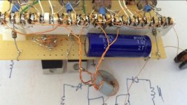
My brief experiments with a 100 KHz heater didn't get past the breadboard stage, so I can't really say how it would have turned out in real life. The tubes in question were 811A's which conveniently do have a 6.3 volt 4 amp heater. The "power supply" was a simple push pull amplifier using a toroids for the driver and output transformers. It was driven from a HP204D audio oscillator which goes up to 1.2 MHz. It kept blowing mosfets, so I gave up. This happened about 15 years ago and the mosfets and toroid cores were old surplus and probably just too slow. It worked OK at lower frequencies but I had to go up to the 100 KHz range to clean up the audible artifacts that could be heard as the frequency was changed.
I had planned to revisit this some day, but I wound up trading most of my old transmitter tubes for TV sweep tubes where I have concentrated my design efforts. I have a nice 30+ watt SE amp running on my workbench right now that uses a new topology to emulate triodes.
UNSET is coming?
My favorite tube is as you might have guessed is the EL/PL519 (my Avatar).
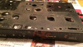
Screen driven a la David Berning (Patent 3,995,226) works really fine. Redesigned a Dynaco Mark VI set this way.
I also designed a HV amp for my ESL's using these tubes (Also G3 driven). I get about 5KV P/P on the output before clipping. This is sufficient enough to drive the Acoustats.
My goal is it to replace these amps with Zotl HV amps as these can be much smaller and more efficient.
The heater wires shouldn't act as antennas as these have a very low resistance to ground plus they are "shielded" by the anode as well in most cases.
At 500Khz i do not have any issues at all (i use HUF75345P FET's).
Attachments

Last edited:
With DC however there is always a field shift, don't you agree?
Yes, there s a field shift - but it is there with ac or dc heating!
With dc it is just a static shift, and any effects are visible in the triode curves (so, nothing to worry about at all).
With ac, the shift is still present, but now the field is bouncing up & down with the low-frequency ac-heat waveform - and that is certainly not an improvement.
The ac-heat waveform causes intermodulation distortion (IMD), as discussed. This is has an unpleasant effect on clarity of sounds, which is completely unnatural (there are no 100/120Hz fundamentals added in natural acoustic instruments or voices). In this way it is notably worse than added harmonics, which occurs in any natural sound-generating source.
George (Tubelab, here) once posted a test for the sound of IMD using a stringed instrument, to be played at increasing levels, all the time watching the IMD levels with a PC spectrum analyser. I find this very instructive for identifying the sound of IMD in ac-heating, and recommend it to constructors wondering about the real effect we are talking about here.
- Status
- Not open for further replies.
- Home
- Amplifiers
- Tubes / Valves
- 6.3V 4A DHT filament supply question