Hi All,
This is my first post to a forum so please bear with me.I found this idea in the book Tonnes of Tone by Kevin O'Conner and thought I would try running my 3 preamp tube filaments on 6vdc to see if it made a difference in the hum of the amp.The article stated it could run up to 5 preamp tubes on a 5vac 2amp winding.I am putting it into a tweed chassis and with it being a little tight I changed the bridge rectifier from a KBP602 to a BR104.I also changed the transistor from a 2n3005 to a TIP3005G.the circuit runs at 6.28 vdc with no load but drops to 4.2vdc when I connect a .45amp load.Any ideas on the problem would be greatly appreciated.Please see the attachment for the schematic.Thanks,Tom
This is my first post to a forum so please bear with me.I found this idea in the book Tonnes of Tone by Kevin O'Conner and thought I would try running my 3 preamp tube filaments on 6vdc to see if it made a difference in the hum of the amp.The article stated it could run up to 5 preamp tubes on a 5vac 2amp winding.I am putting it into a tweed chassis and with it being a little tight I changed the bridge rectifier from a KBP602 to a BR104.I also changed the transistor from a 2n3005 to a TIP3005G.the circuit runs at 6.28 vdc with no load but drops to 4.2vdc when I connect a .45amp load.Any ideas on the problem would be greatly appreciated.Please see the attachment for the schematic.Thanks,Tom
Attachments
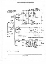
Theory says that you should get sqrt(2)*VAC on the reservoir cap. However, this assumes that the rectifier conducts infinite current for only an instant. In reality, you end up with 1.2~1.3*VAC. So on your reservoir cap, C4, you should see about 5*1.25 = 6.25 V.
At no load, you'll get very close to that voltage on the output. However, as the load current increases, the transformer output voltage will start to droop slightly due to losses in the transformer. In addition, Q1 starts drawing base current. Now, I don't recall the hfe of a 2N3055 off the top of my head, but I bet it's lower than 50 - especially at low collector currents. The increase in base current will cause the voltage across R6 to increase, so the base voltage on the 2N3055 drops. As the base voltage drops, the emitter voltage will drop as well. In addition, as output current is drawn, ripple voltage develops on the reservoir cap. As the regulator doesn't have any headroom (input voltage is the same as output voltage), this ripple will go straight through to the output which begs the question, why have a regulator there in the first place.
I'm sorry to say, but that design is fundamentally flawed if it's designed to operate off of a 5.0 V winding.
If you want the circuit to work with minimum changes, I suggest adding a 6.8 V zener diode in parallel with C5 (cathode of the diode to the positive terminal of C5). That'll give you a fairly stable 6.1~6.2 V output voltage. The drawback will be that the output voltage will depend on the temperature of the 2N3055, but as the transistor heats up, the output voltage will rise (about 2 mV per degree C) so you may get closer to 6.3 V out as the supply heats up. You still need to provide a higher input voltage, though. You might be able to get by running off of a 6.3 V winding, but I'd suggest using an 8~9 VAC transformer.
If you want to be more exact about it and get 6.3 V across temperature, I suggest looking at the LM317. It should be available at just about any electronic component shop near you. You'll need to provide a few external components (two resistors, one capacitor) and put it on a heat sink. You still need to provide a higher transformer voltage, though... The LM317 needs about 2.5 V across it to regulate properly.
Depending on what kind of transformer you're operating with, you could also add a winding to it... Like I did here.
~Tom
Last edited:
I guess the idea was to use transistor as smoothing ripple (active cap), but considering low starting voltage proposed design is not a good one.
Even using 317 s bad solution because of sharp cutoff when voltage sags below adjusted value (in this case) maybe some low drop regulator like 1084 (less then 0.8V drop @1A)or something even better, mayybe...
I would use better active cell with PNP serial transistor (so you don't loose 0.7V Vbe at least), just pure huge cap with some inductor in series before to smooth high diode/winding peak current spikes, or little step up (boost) smps (i know i know 😱😱 nooise, but actually it is not that bad)...
You may be making this too hard. 5vac through a bridge rectifier will give you 7v -
the voltage drop across the bridge which will probably be ~1v. So you probably
will end up with about 6vdc. Usualy we forgit about this voltage drop when dealing
with higher voltages but in this case it's an inportant factor.
the voltage drop across the bridge which will probably be ~1v. So you probably
will end up with about 6vdc. Usualy we forgit about this voltage drop when dealing
with higher voltages but in this case it's an inportant factor.
Hello,
6 Volts DC from a full wave bridge rectifier from a 5 V AC winding is not going to happen. You may not get 5V DC. Somehow I cannot remember that I cannot even get 6 V DC from a 6.3 volt AC transformer. Remember the typical diode drops over 1 volt and a full wave bridge rectifier drops voltage across two diodes or nearly a 3 volt drop (real world). You might get a voltage doubler to work but that is brute force and will require not only twice the number of capacitors, big ones because of the stacked current peaks with the big valley in between.
I use 8 Volt AC transformers for 6.3 Volt heaters, that leaves a little room for drop out on the regulator.
DT
All Just for fun!
Make a full wave doubler using shottkey diodes and feed the regulator with that. At such low voltage large value capacitors are quite small and it does not matter it there is one or two volts of ripple, the regulator has enough headroom to remove it.
Please realize that if a transformer is rated for 6.3VAC, then it will likely be higher than that with no load. Proper manufacturers compensate for typical loading. But, remember this is RMS. 6.3VAC is really around 8.9Vp or 17.8Vpp. When passed through a bridge rectificer; there are some voltage drops in the diodes (silicon is 0.7V). This is a greater percentage of your voltage than it would be for a high voltage supply. The output of the rectifier should be 8.9V ripple DC at 120Hz with no losses in the bridge rectifier and no load if the transformer puts out 6.3VAC.
If you are coming up short on your supply voltage, you can use a voltage doubler into an adjustable voltage regulator or just a voltage divider network using resistors. Please take wattage and heat dissipation into consideration. Good luck!
If you are coming up short on your supply voltage, you can use a voltage doubler into an adjustable voltage regulator or just a voltage divider network using resistors. Please take wattage and heat dissipation into consideration. Good luck!
Be careful you don't overheat the secondary winding and the transformer.
Heater current is continuous duty. The transformer secondary must be rated to supply this continuous duty.
A 6.3Vac 500mAac secondary can supply a 500mAac heater continuously.
A 5Vac 500mA secondary when rectified and smoothed can only supply ~250mAdc continuously.
You must choose a secondary AC current rating at least double the total heater current requirement. Preferably choose 4times heater current to maintain cool running of the secondary winding.
At these low voltages the Vf of the rectifying diodes is significant.
Choose your voltages and diodes to give the output power you really need.
yor best bet is to forgo the regulators, use big caps, use schottky bridge for lower losses and see what happens....
depending on transformer construction, a heater winding rated at 2amps can usualy be drained 3amps without serious problem....
depending on transformer construction, a heater winding rated at 2amps can usualy be drained 3amps without serious problem....
A 5Vac 500mA secondary when rectified and smoothed can only supply ~250mAdc continuously.
Andrew,
A gross overgeneralization.
Look at Sowter's website How to Specify HT Windings to see how primary and secondary currents relate with different ways of rectifying and filtering.
Having looked at this inappropriate HV from Sowter, I see that diagram second from top can be adapted to suit a 6.3Vac secondary.
The formulae apply to Sowter's transformers and maybe only to their HV transformers.
Let's take the 6.3Vac winding and rectify it and feed it into a capacitor input filter.
The output voltage when no current is drawn is given by Vdc = Vac * 1+regulation * sqrt(2) - 2* diode Vf (@ near zero current, there is some leakage current passing the diodes).
The current rating for this arrangement must take account of the capacitor input filter and each manufacturer quotes the de-rating that should be applied to their transformers. Sowter show their factor in inverse form: 1.61 is equivalent to 0.621
Let's now apply that to the output voltage and put in some values for loaded voltages and corresponding currents.
6.3 * 1+7% * 1.414 - 2 * 0.5Vf ~8.5Vdc
When significant current is drawn the DC voltage will drop. Let's assume it drops to 7.5Vdc +- half the ripple voltage resulting from the smoothing capacitor not having infinite capacitance.
The output power when drawing 500mA is 7.5 * 0.5 = 3.75W
The transformer must be rated for secondary capability using rated output voltage * rated output current * 1.61
For our 6.3Vac secondary we have 6.3V * 1.61 * rated output current as the secondary Power rating.
The output power required is 3.75W.
The secondary winding AC current rating must be 3.75 / 6.3 * 1.61 ~ 0.96Aac.
Note the secondary needs to be rated at ~ double the DC current drawn from the capacitor input filter.
At this current the transformer will be running at maximum continuous duty. It will run at the manufacturers maximum rated temperature rise.
If you require cooler running then a higher secondary AC current rating should be used. I and others suggest a factor of two times.
That results in a 2Aac rated secondary to provide a cool running 500mAdc supply
Andrew,
I can follow your story until, at the end, you state: "the secondary winding AC current rating must be (3.75 / 6.3) * 1.61 = ~0.96 Aac. That is a creative way to reach your "double current" target!
Assume you need a filament transformer whereby the secondary must feed a bridge supply, and you finally want a 6.3 DC voltage with 0.5 A current capability.
Assume there is 2 * 0.7 V drop across the bridge, we need 5,45 VAC at the secondary.
This 5.45 VAC is under load, so 5.45 * 1,414 - (2*0.7) = 6.3 VDC.
DC output power is 6.3 * 0.5 = 3.15W.
The secondary winding AC current therefore must be 3.15 / 6.3 * 1.61 = 0.805 A.
In your example you start with 6.3 VAC, so you end up with a too high 7.5 VDC which is 3.75 W power where you don't need more than 3.15 W.
Designing these kind of transformers I calculate with 3A per square mm for the wire, and a core excitation not over 1T. IMHO this is good practice, unless you want to please the copper vendors.
These transformers are quiet and don't get hot.
Actually it does not make sense to argue about the voltage - current affair; formulas apply and work.
Someone buys whatever power supply transformer and finds out it gets hot, too hot for his taste.
Next time he needs a transformer for the same application and specifies double currents, and finds out it does not get that hot. He is happier with this one.
Only thing that can be concluded is that these first and second transformers were designed with different requirements, especially in terms of temperature.
Say you need a power supply transformer with 20 watts of secondary power.
It is designed such that the transformer can supply 40 watts (twice the current), but you use it for your 20 watts application; it is wound for a core excitation of 1.6T.
A second transformer, also to supply 20 watts, is designed to be able to deliver the current for the application, but is wound for a core excitation of 1T.
Practice will learn that you need a 40 watt core because the 1T transformer requires more winding space.
So you have two transformers, wound differently but for the same duty.
Which one would you prefer?
i would always chose the one that doesn't get hotter.....in all my transformer builds, my priority has always been low exciting currents....
lamination thickness was mentioned earlier, for 0,5mm lams i go lower than 0.9T while for 0.35mm lams i go for 1T and higher for GOSS lams of the same 0.35 thickness.....
lamination thickness was mentioned earlier, for 0,5mm lams i go lower than 0.9T while for 0.35mm lams i go for 1T and higher for GOSS lams of the same 0.35 thickness.....

Any 6.5VDC 1.5A regulated supply from 5VAC please. Mr. Elvee to feed.If you want to squeeze out the last drop of juice from your 5V AC, the way to go is synchronous rectification.
In this example, the voltage drop is only 70mV:
https://www.diyaudio.com/community/...-too-slow-7seconds.389351/page-5#post-7105397
- Home
- Amplifiers
- Power Supplies
- 6.3 filament from 5vac winding