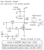
I have built this 5W Class A power amp designed by Mark Houston and feel happy with it's sounding performance. I am wondering now if I could use 2SK1058's complementary pair 2SJ162 to build one more power amp as the supplier sell them together. Please advice.
Attachments
Member
Joined 2009
Paid Member
I think SSDIY is looking for a way to build another amp not improve this one. The answer lies in using the complimentary part as an active device with resistive load of course, only you have to put the active device on top and the resistor underneath.
Hi guys
Thank you for all your inputs. What I mean is to replace the 2SK1058 by 2SJ162 and apply a -24v to it. Other parts and components remain unchanged. Would the circuit work properly with this change? Please advice.
Thank you for all your inputs. What I mean is to replace the 2SK1058 by 2SJ162 and apply a -24v to it. Other parts and components remain unchanged. Would the circuit work properly with this change? Please advice.
No, it is made for both 2SK1058 and SJ201.
But sure is possible to make such circuit.
It will be kinda upside down because 2SJ162 is P-channel transistor.
But sure is possible to make such circuit.
It will be kinda upside down because 2SJ162 is P-channel transistor.
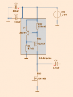
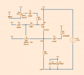
Here is a version for 2SJ162.
Note that power supply V+ is connected to GROUND.
And so GROUND is the upper part.
But as long as you note polarity of electrolytic capacitors
it should not be a problem.
A stereo system should be 2 such with 2SJ162
as 2SK1058 has a bit different caracteristic from 2SJ162.
Note that power supply V+ is connected to GROUND.
And so GROUND is the upper part.
But as long as you note polarity of electrolytic capacitors
it should not be a problem.
A stereo system should be 2 such with 2SJ162
as 2SK1058 has a bit different caracteristic from 2SJ162.
Attachments
Here is a version for 2SJ162.
Note that power supply V+ is connected to GROUND.
And so GROUND is the upper part.
But as long as you note polarity of electrolytic capacitors
it should not be a problem.
A stereo system should be 2 such with 2SJ162
as 2SK1058 has a bit different caracteristic from 2SJ162.
Hi lineup
Thank you very much for the 2SJ162 schematic. It is clear and very helpful. I want to build two of this amps for my bi-amp speaker system one amp use 2SK1058 and the other amp use 2SJ162.
Member
Joined 2009
Paid Member
With the +24V and -24V supplies, you may be able to bridge them for higher power if wanted in the future (you'll need to provide for signal inversion somewhere)
With the +24V and -24V supplies, you may be able to bridge them for higher power if wanted in the future (you'll need to provide for signal inversion somewhere)
Hi Bigun
It is a good idea to bridge the amp to get more power to driver the speakers. Thank you for reminding.
Keep in mind that once you bridge this circuit its no longer single-ended and 2nd harmonic is suppressed leaving a prominent 3rd. Also, you still have to come up with the bias current to run double peak voltage into whatever load.
Hi,
a 1058 or a 162 can easily be biased to ~1.3 to 1.4A
This will give ~8W into 8ohms from your +24V supply.
Adding a complementary transistor to convert the circuit to push-pull would be better than going balanced.
Pass has lots of variations on SE, PP, Balanced.
a 1058 or a 162 can easily be biased to ~1.3 to 1.4A
This will give ~8W into 8ohms from your +24V supply.
Adding a complementary transistor to convert the circuit to push-pull would be better than going balanced.
Pass has lots of variations on SE, PP, Balanced.
Hi Andrew.
I'm assuming we are still using the original circuit as in post 1.
To run 1.4A bias current, the 15R resistor will need to be changed to 8.6R.
The peak output current is now 8.6R plus 8R (assuming 8R speaker load), with 12 V peak. Ie 12 volts across 16.6R = 0.72A
Peak power is Isquared times load so = 4Watts, RMS power 2 W.
This is a somewhat inefficient circuit.
You are spot on with the suggestion of going push pull, you'd get the full 12 V peak across the 8R load (assuming no losses), ie. 1.5 A which would translate to 9W rms.
Taking another look at the circuit, the design parameters are quite wrong.
The 'mid point' output voltage should not be 12V. For maximum output into 8R it should be at 8 Volts. This would instantly quadruple the power output!
We'd get an earth shattering 4W rms. (with the original 15R resistor)
The 'mid point' output voltage should not be 12V. For maximum output into 8R it should be at 8 Volts. This would instantly quadruple the power output!
We'd get an earth shattering 4W rms. (with the original 15R resistor)
You are right. Should be lower than 12 Volt.Taking another look at the circuit, the design parameters are quite wrong.
The 'mid point' output voltage should not be 12V. For maximum output into 8R it should be at 8 Volts. This would instantly quadruple the power output!
We'd get an earth shattering 4W rms. (with the original 15R resistor)
The original that people build has got output at 12 Volt.
Which is not optimal.
I should have done the sums. I've been bad, now where did I put the Dunce's hat?The peak output current is now 8.6R plus 8R (assuming 8R speaker load), with 12 V peak. Ie 12 volts across 16.6R = 0.72A
Peak power is Isquared times load so = 4Watts, RMS power 2 W.
This is a somewhat inefficient circuit.
I have not used resistor loading in a power amp and so momentarily forgot the halving of efficiency that comes with going from PP to SE with CCS and a further halving when going from SE CCS load to SE resistor load.
Arithmetic is a very powerful tool and I do know better than to ignore it.
Keep in mind that once you bridge this circuit its no longer single-ended and 2nd harmonic is suppressed leaving a prominent 3rd. Also, you still have to come up with the bias current to run double peak voltage into whatever load.
Hi Andrew
May I ask what is the different between bridged and balanced if I make this amp a balanced (4 boards of this circuit one for + phase signal and one for - phase signal x 2 channel for a stereo 2 channel amp)? Please advice as my other thread in this forum I am going to change my entire stereo system from RCA to XLR.
- Status
- Not open for further replies.
- Home
- Amplifiers
- Solid State
- 5W Single Ended Class A Power Amp From Mark Houston