Given the limitations of tube rectifiers in terms of current, is there any reason why the tube rectifier isn’t used to drive a (or pair of) bypass shunt triode?
The bypass shunt then allows when he AC waveform allows, additional current to be supplied to the B+ rail without going through the rectifier? The triode is shut off before the rectifier itself passes zero transition.
The bypass shunt then allows when he AC waveform allows, additional current to be supplied to the B+ rail without going through the rectifier? The triode is shut off before the rectifier itself passes zero transition.
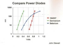
The voltage drop in 5U4 is about 20V depending on the current demanded, following the Child's law. And a SS diode has rougly 1V, so a parallel of both is useless as tube diode can't conduct any electron with 1V aceross it.
NickKUK and Osvaldo de Banfield.
A Shunt Triode is one thing.
A Shunt Solid Stage Diode is another thing.
Which are you putting in parallel with a Tube Rectifier?
And . . . how about posting a hand drawn schematic, so we can be sure what the question is about?
A Shunt Triode is one thing.
A Shunt Solid Stage Diode is another thing.
Which are you putting in parallel with a Tube Rectifier?
And . . . how about posting a hand drawn schematic, so we can be sure what the question is about?
Doesn't matter.
A solid state diode would have a much lower voltage drop than any tube rectifier, so that the tube would hardly conduct at all.
A triode in parallel with a tube rectifier could be set up with a proper control circuit to shunt some current around the tube rectifier. All but a few tube triodes have far more voltage drop than a typical tube rectifier under similar current conditions, so it's assistance would probably be less than simply adding a second tube rectifier in parallel with the first.
A "lossless diode" or "ideal rectifier" setup similar to some single chip solutions (see the LT4320) currently available for low voltage high current applications could be constructed with a 4 quadrant controller and some mosfets. It would replace the tube rectifier with no loss or reverse recovery effects.
Ideal Diode Bridge | Analog Devices
NickKUK and Osvaldo de Banfield.
A Shunt Triode is one thing.
A Shunt Solid Stage Diode is another thing.
Which are you putting in parallel with a Tube Rectifier?
And . . . how about posting a hand drawn schematic, so we can be sure what the question is about?
The question is confusing, but for me, he is trying to parallel two diodes, one VT & the other, SS.
I read TRI-ode so no sure where the discussion about DI-odes comes from.
Also no mention of SS at all, while there is mention of "conduction at certain moments and not others":
I think nickuk is trying to describe a synchronous rectifier.
Active rectification - Wikipedia
The basic idea is fine, although in this particular case a triode is worse than a diode.
Also no mention of SS at all, while there is mention of "conduction at certain moments and not others":
The triode is shut off before ......
I think nickuk is trying to describe a synchronous rectifier.
Active rectification - Wikipedia
The basic idea is fine, although in this particular case a triode is worse than a diode.
The topic of augmenting the performance of a rectifier diode is not uncommon across the decades.
NickKUK, in a particular application you seem to be concerned about the peak current portion of the diode waveform getting to an excessive level for a particular diode. Perhaps that concern can be elaborated on so that we have some base from which to offer comments? The 5U4 does have a 1Apk continuous rating - is that being exceeded in the application?
NickKUK, in a particular application you seem to be concerned about the peak current portion of the diode waveform getting to an excessive level for a particular diode. Perhaps that concern can be elaborated on so that we have some base from which to offer comments? The 5U4 does have a 1Apk continuous rating - is that being exceeded in the application?
Last edited:

This is more 'can it be done' but probably not best communicated due to travel fatique.
The simple thing would be to parallel secondaries, each with their own rectifier. However I was wondering if there's a way to have one secondary (less iron complication) by increasing the current capacity of rectification.
I'm aware of active rectifications from my studies in SMPS design, typically used in higher power PFC and output stages where efficiency is required.
However I would have not expected a trick like this to have been missed in the golden age of tubes so I missed the obvious HT across the triode (been looking too much at BJTs etc recently).
I suggest there is no practical issue for starters. If the concern is that a valve diode is going to exceed its peak continuous current spec, then change to another valve diode, or double up on the valve diode (a quite common situation for higher power amps). There is nothing easier than that scenario imho. There are different vintage valve diodes like mercury, with effectively a flat on-voltage, but again that adds complexity.
Synchronous isn't quite what you are asking afaik, as that normally implies just a gated diode, not a parallel combination of diodes of which one diode is naturally commutating current and the other is gated such that it only comes in to play when rectified current exceeds say a certain level (assuming capacitor input filter with a high crest-factor current waveform), or some other control parameter like on-voltage.
Synchronous isn't quite what you are asking afaik, as that normally implies just a gated diode, not a parallel combination of diodes of which one diode is naturally commutating current and the other is gated such that it only comes in to play when rectified current exceeds say a certain level (assuming capacitor input filter with a high crest-factor current waveform), or some other control parameter like on-voltage.
Last edited:
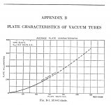
Plate current is low , price high 😀 Much weaker than a diode .
I see no point in this "idea" with triodes .
I see no point in this "idea" with triodes .
Last edited:
If you really want to chase the low loss, high current tube rectifier rabbit hole dig into the past where thyratrons were used for rectifiers.
The thyratron is a gas filled switching tube. It is off until triggered but one triggered (the gas ionized) it turns into a near short. Big ones can pass amps of current. Once the AC cycle crosses zero there is no voltage to keep the gas ionized, so the "arc" goes out and the cycle starts over.
These are the vacuum tube equivalent of an SCR, and were used in high voltage, high current power supplies for years.
The "gas" is often vaporized mercury so the caveats are similar to mercury vapor rectifiers, which are another way to get near low loss at high voltages and currents.
I tend to favor a big silicon or SiC chip for these kind of things.
- Home
- Amplifiers
- Tubes / Valves
- 5U4 with triode bypass