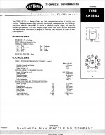
Well, the scenario you describe (Vp = 150V, Ip 25mA, 60R Rk) is precisely one of the typical operation examples in the 5842 datasheet except it uses 0V on the grid.
I will see if I have suitable resistors to achieve Vp of 150V and will post back.
Btw, one thing that always confuses me in datasheets is whether Vp in "typical operation" sections means the actual voltage seen by the plate or if it's the voltage across the tube. If the latter, I'd need something like 151.5V on the plate and 1.5V on the cathode to get 150Vpk.
Attachments
Last edited:
Well, the scenario you describe (Vp = 150V, Ip 25mA, 60R Rk) is precisely one of the typical operation examples in the 5842 datasheet except it uses 0V on the grid.
Sorry, it says "Cathode bias resistance" = 60 ohms, which with 25mA drawn across it would drop 1.5V. That is -1.5V grid bias achieved through cathode bias. Agrees exactly with the load line on the plate curves.
Btw, one thing that always confuses me in datasheets is whether Vp in "typical operation" sections means the actual voltage seen by the plate or if it's the voltage across the tube. If the latter, I'd need something like 151.5V on the plate and 1.5V on the cathode to get 150Vpk.
I think it means voltage measured from plate to cathode, with the cathode grounded and grid bias being applied from a negative voltage supply or a battery, or in other words, fixed bias.
--
OK, thanks. That's very helpful. I just realized that I don't think I can achieve 150V @ 25mA. Right now, with 139Vp and a 60R resistor, I'm already at 1.6Vk. In my records, using the 60R cathode resistor I had one configuration that was 145Vp, 1.75Vk, which is 29.17mA and 4.18 watts dissipation (93% of max). Not sure why that's so far off the datasheet. I could probably get to 150Vk/25mA with a different cathode resistor value.
Like I've found, these high gm RF tubes vary quite a lot in their actual characteristics. It's because their internal parts are so small and fit so close together (tightly wound grid wire on frame grid) that even small deviations cause large differences in parameters. I believe that's why it's been difficult for me to find matched pairs of the tubes I'm using in my headphone amp (I'm using a high gm, frame grid RF pentode, wired triode).
Your actual 5842 tubes seem to draw more current than the 'bogey' tube depicted in the data sheet. That's not a big surprise.
--
Your actual 5842 tubes seem to draw more current than the 'bogey' tube depicted in the data sheet. That's not a big surprise.
--
Hmm. I wonder if it could also be the 5.5K primary winding of the OPT that is drawing more current out of the tube than would be expected on the datasheet. After all, the 5842 was designed as an input tube -- not an output tube connected to a transformer. The datasheet page I posted above lists "Plate resistance 1700 ohms" for the 150V/25mA op point. Does that mean the internal resistance of the plate itself or the plate load resistance? If it's the plate load resistance (impedance), then it's a rather different line. I plotted them -- 5.5K load in purple, 1.7K load in blue, attached.
Attachments
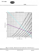
1.7k ohms is the internal plate resistance of the tube itself.
The load resistance would normally be between 2x and 5x that value.
A load resistance (Rp or Rload) that is 2x the internal plate plate resistance (rp) yields the highest power output from the triode.
Rp (or Rload) that is 4x or more than the tube's rp will let the triode swing more volts +/- from the bias point with lower distortion, but will not be able to dump as much power (voltage x current) into the load.
5.5k/1.7k = 3.235
That's not the lowest distortion load, but should be fine.
--
Check this out: The Valve Wizard -Single Ended
And this: The Valve Wizard
In the quieter atmosphere of the morning I noticed that the 5842s are indeed picking up ambient electrical noise since removing the four grid stoppers. I also heard a faint hiss and squeal (oscillation?), plus it would emit a faint static or soft brushing sound when I would scroll a web page on my computer.
I tried adding a single 200R grid stopper to one pin, which changed nothing. Then I tried rongon's suggestion in post #37 to use a single 1K grid stopper to pin 5, and then connect pins 5 and 7 with a jumper (I just screwed the resistor lead to both tabs on the breadboard), since that would tie all the grid connections together. Ambient noise is almost entirely eliminated, although if I listen really hard while the air conditioning is off, I can still hear the static when scrolling a web page if I'm specifically listening for it.
Not a big deal, since it's inaudible when music is playing. But since the final build of this amp is intended to play a CD player -- not a computer -- I'd best take precautions about motor noise. I'll be adding the four grid stoppers back in, to see if I can still here the computer-induced static.
It's too bad, because removing the stoppers really did improve musical clarity.
Then I tried rongon's suggestion in post #37 to use a single 1K grid stopper to pin 5, and then connect pins 5 and 7 with a jumper (I just screwed the resistor lead to both tabs on the breadboard), since that would tie all the grid connections together.
I'm not sure from what you wrote, but just in case...
In order for a grid stopper resistor to be effective, you want to install it so that the body of the resistor is as physically close to the grid pin on the tube socket as possible. You do not want to have a grid stopper resistor installed on a circuit board or tag strip with a wire running from the resistor's location to the grid pin on the tube socket. The resistor should be soldered directly to the grid pin on the tube socket, with the shortest length of lead wire possible. The ideal would be to use a surface mount resistor soldered directly onto the grid pin on the tube socket, but that is usually impractical.
If you already knew that, then never mind.
Thanks for the reminder, rongon. Yes, I'm aware of that and imagine that much of the noise I'm hearing -- faint as it is and likely owing to the, uhh... less than optimal unenclosed breadboard situation with a ratsnest of flying leads everywhere -- will go away by virtue of best practices in the final build (chassis and other parts are on the way).
Speaking of noise, I'm now chasing down some 60Hz buzz with some 60Hz hum mixed in. It sounds like a very, very faint version of this, which is likely from ground loop induced by the ratsnest: YouTube
Re: hum -- Since the EZ81 and 5842s are currently AC heated, I thought AC hum might be a contributor. Making virtual center taps with 200R resistors changed nothing. I'm going to try 500R hum pots (per Valve Wizard) on the 5842s but will first wait to see how it sounds in the final build. It's possible that proper heater wiring practice and chassis layout will take care of it. Plus, the buzz is what's dominant, and it will be difficult to assess hum until that's gone.
I then tried moving the PT around and changing its orientation. It seems to interact with the metal-encased oil capacitors in the power supply. If it's close to them, there's a little more hum. If the laminations are vertical and facing them, there's louder hum, especially when the top of the PT is facing them. If I roll the PT so that the top laminations are horizontal and facing the capacitors (like a laydown transformer), the hum goes away. It also goes away if the end bells are facing the capacitors.
What's interesting is that in the laydown orientation, the PT can be as close to the capacitors as I like with no apparent additional hum. With the PT vertical and the bells facing the capacitors, a faint hum is induced when it gets within about an inch, but beyond that inch there's no perceived interaction.
So, in the final build, bells facing the caps with as much distance as possible. And this makes me want to use laydown transformers in all my future builds. In fact the PT is small enough that I could mount it inside the chassis oriented like a laydown PT.
NB: PT orientation and proximity to the chokes and rectifier tube had no audible effect.
Last edited:
So weird.
I removed the grid stoppers again just to A/B the sound quality and all buzz and hum have vanished. I am listening to a totally black background and even the "brushing" sound from scrolling web pages is gone.
I must have had something poorly grounded during all my trials today and made a better connection by accident this last time.
Moving the PT closer to the capacitors still induces hum though. That might improve when they are chassis-grounded.
Last edited:
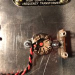
I've started the final build and am currently working on the heater wiring. The 5842 heater pins are 3 (black wire) and 9 (red wire), which are pretty much across the tube from one another (see attached image). Following Morgan Jones, I've run one wire across the tube, rather than making a loop or loose opening around the tube base.
My plan is to run the signal input to pin 2 (just left of pin 3), which has no connection in the tube, and fan out the grid stopper resistors from there to pins 4, 5, 7, and 8. That would allow me to keep the resistors right up against the pins as people have advised earlier in this thread.
My concern is that the signal paths would cross so close to that heater wire. Does this seem like a good way to go, or ought I perhaps to connect the grid stoppers from a location further from the heater wires, like the 2-tab strip shown in the picture?
Attachments
1.7k ohms is the internal plate resistance of the tube itself.
The load resistance would normally be between 2x and 5x that value.
A load resistance (Rp or Rload) that is 2x the internal plate plate resistance (rp) yields the highest power output from the triode.
Rp (or Rload) that is 4x or more than the tube's rp will let the triode swing more volts +/- from the bias point with lower distortion, but will not be able to dump as much power (voltage x current) into the load.
5.5k/1.7k = 3.235
That's not the lowest distortion load, but should be fine.
--
Check this out: The Valve Wizard -Single Ended
And this: The Valve Wizard
If Rp is 1,700 ohm at the operating point, actual Rp in this circuit with 60 ohm Rk will be approximate to 4,300 ohms.
The 5,500 ohm spec on the transformer is simply the inductive reactance at some frequency. If you know this frequency you can work out the primary inductance, and it is this which loads the tube - and this impedance will increase with frequency and be much much higher than 5,500 ohms. For example, if the 5,500 is at 20Hz, the inductance will be ~44H, and this inductance will present a plate load greater than 2,800,000 ohms at 10kHz.
If the 5,500 ohm spec is at 20Hz, Rp at 4,300 has LF -3dB at 16Hz and -1dB at 60Hz.
Hanze.
Last edited:
If Rp is 1,700 ohm at the operating point, actual Rp in this circuit with 60 ohm Rk will be approximate to 4,300 ohms.
2200uF in parallel with the 60 ohm Rk would bring rp back down to about 1700 ohms.
What is the expected voltage drop across that 60 ohm Rk?
25mA x 60 ohms = 1.5V.
If you can live with lower current draw through the tube, maybe a red LED would work as the cathode load. Pick a red LED with forward V drop of about 1.7V. Or if the expected plate current is more like 20mA, then an IR LED would work (Vf = 1.2V or thereabouts). Make sure the LEDs you choose are rated for >20mA continuous (they're out there; just have to be careful to check the LED's spec sheet).
As far as wiring the grid stoppers, that's a very good question. I think I would solder the input wire to the lower lug on the tag strip, and run the resistors from there. That would help keep the input wire away from the black heater wire. But I could be wrong about that. The grid stopper resistors would still end up pretty close to the black heater wire.
It might help if you can find shorter bolts to fasten the tube socket to the chassis. The extra length of bolt may get in the way of the signal wiring.
--
Last edited:
Thanks for that explanation Hanze. I've never heard about that before so I'll have to look into it.
On both of the two 25uF oil capacitors, one of the leads is marked red (attached). Do you think that's because the caps are polarized?
I don't think they are. It says nothing about polarization, and the only voltage rating given in the writing on the can is 330VAC.
On both of the two 25uF oil capacitors, one of the leads is marked red (attached). Do you think that's because the caps are polarized?
I don't think they are. It says nothing about polarization, and the only voltage rating given in the writing on the can is 330VAC.
Attachments
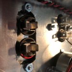
I don't know for certain, but usually when there's a marked terminal on a non-polar capacitor, that indicates which terminal is wired to the capacitor's 'outer foil.'
Where To Connect the Outside Foil on Capacitors
--
A 330VAC rated capacitor is almost certainly good for 400VDC.
Where To Connect the Outside Foil on Capacitors
--
A 330VAC rated capacitor is almost certainly good for 400VDC.
My understanding is that all capacitors with a wound construction will have an outer foil (where the end of the foil is on the outside of the 'jelly roll' wrap) and an inner foil.
Metallized film capacitors have the conductors sputtered onto the thin sheets of dielectric. Film and foil caps have a thin dielectric film and a thin metal film rolled into a jelly roll. I don't know which type of construction those oval oil-filled caps use. I think the modern ones are metallized film. Either way, yes, I think those oil caps will have an outer foil and an inner foil.
Be careful which end of your circuit you consider to be 'ground.' You want the outer foil connected to the *lowest impedance* node. That can sometimes mean the outer foil should be connected to the plate of the tube. It depends on the circuit and what function the capacitor is performing.
For a power supply decoupling cap, 'ground' is obvious. It's the 0V rail. The outer foil (marked terminal) goes to 0V, the inner foil goes to B+.
Here's an article I found that discusses what the marked terminal means on a motor-run cap (which is what you have there).
Identifying Motor Capacitor Terminals | HVAC Troubleshooting
It says there, "(M)anufacturers of oil-filled capacitors will identify one terminal with an arrow, a painted dot, or by stamping a dash in the capacitor can, Figure 11–27. This identified terminal marks the connection to the plate that is located nearer to the metal container or can."

I think the connection to the 'plate' (foil) that is closest to the capacitor's external metal can would be the 'outer foil.' (I could be wrong, but I think that's right.)
--
Metallized film capacitors have the conductors sputtered onto the thin sheets of dielectric. Film and foil caps have a thin dielectric film and a thin metal film rolled into a jelly roll. I don't know which type of construction those oval oil-filled caps use. I think the modern ones are metallized film. Either way, yes, I think those oil caps will have an outer foil and an inner foil.
Be careful which end of your circuit you consider to be 'ground.' You want the outer foil connected to the *lowest impedance* node. That can sometimes mean the outer foil should be connected to the plate of the tube. It depends on the circuit and what function the capacitor is performing.
For a power supply decoupling cap, 'ground' is obvious. It's the 0V rail. The outer foil (marked terminal) goes to 0V, the inner foil goes to B+.
Here's an article I found that discusses what the marked terminal means on a motor-run cap (which is what you have there).
Identifying Motor Capacitor Terminals | HVAC Troubleshooting
It says there, "(M)anufacturers of oil-filled capacitors will identify one terminal with an arrow, a painted dot, or by stamping a dash in the capacitor can, Figure 11–27. This identified terminal marks the connection to the plate that is located nearer to the metal container or can."
I think the connection to the 'plate' (foil) that is closest to the capacitor's external metal can would be the 'outer foil.' (I could be wrong, but I think that's right.)
--
OK, thanks for that. In the final build I've got my red dot terminals connected to ground in the PS. On the breadboard they were connected to HT.
I stayed up late to finish the build last night. The music sounds very good but now I'm chasing down a loud 60Hz "angry insect" buzz, which is probably grounding related.
I tested the whole circuit for connectivity and re-soldered the tube socket pins just to make sure.
I thought maybe the chokes were too close to the metal oil caps, but moving them around changed nothing.
I thought maybe there was a ground loop between the HT center tap wire, which was connected to the ground tab of the first PS capacitor, and the ground point. Removing the CT wire eliminated buzz but also made the music really quiet and distorted. So soldered the CT wire directly to the ground pin of the IEC inlet just to see if a different location changed anything, and the buzz was back as before.
The buzz gets louder and softer with the volume control, so it could be related to that. Anyway I'll have to return to this later today.
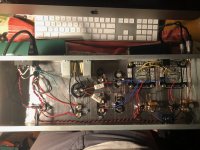
Edit: here's a pic of the build. I tried a ground bus that starts at the input jacks and connects to the chassis at one point near the PT and IEC inlet. It snakes down the center while the PS and signal components branch into it. Bad idea? I was going to do a straight bar along the chassis corner, with everything connecting in one direction, but this seemed more efficient.
I stayed up late to finish the build last night. The music sounds very good but now I'm chasing down a loud 60Hz "angry insect" buzz, which is probably grounding related.
I tested the whole circuit for connectivity and re-soldered the tube socket pins just to make sure.
I thought maybe the chokes were too close to the metal oil caps, but moving them around changed nothing.
I thought maybe there was a ground loop between the HT center tap wire, which was connected to the ground tab of the first PS capacitor, and the ground point. Removing the CT wire eliminated buzz but also made the music really quiet and distorted. So soldered the CT wire directly to the ground pin of the IEC inlet just to see if a different location changed anything, and the buzz was back as before.
The buzz gets louder and softer with the volume control, so it could be related to that. Anyway I'll have to return to this later today.
Edit: here's a pic of the build. I tried a ground bus that starts at the input jacks and connects to the chassis at one point near the PT and IEC inlet. It snakes down the center while the PS and signal components branch into it. Bad idea? I was going to do a straight bar along the chassis corner, with everything connecting in one direction, but this seemed more efficient.
Attachments
Last edited:
These kinds of problems are usually grounding-related.
I found that on my last build, sticking to a set of well-defined rules for grounding yielded a quiet amp.
1) Separate the 'safety' ground from the signal ground. That means from the IEC inlet socket, the green/yellow 'earth' wire should be connected to chassis right there. Use a sharp star washer and a bolt with a couple of nuts, and tighten them well. You want that connection to have zero resistance.
2) The signal ground should be connected to chassis at *one* location only, and that should be at the *input*. I put a bolt with star washer near my input jacks, and made that my input 'star ground' location. That's my signal 'chassis ground.'
3) I ran a copper wire ground bus back from that input star (that star ground point is the one and only chassis ground point for signal ground) back to the decoupling capacitors.
4) I arranged my power transformer, rectifier diodes, power transformer center-tap, reservoir capacitor and power supply choke in a tight grouping at the far end of my chassis from the audio circuitry (tubes, OPTs, input/output jacks). These noisy/high-current power supply parts all connect to a single point at the far end of the ground bus. This point is not connected to chassis at that far end. It finds its way to ground through the signal ground bus going to the signal/chassis star ground point at the input end of the amp.
The idea is that the audio circuit grounds all have the shortest possible path to the chassis ground. (The audio circuit grounds are connected right to the chassis ground/star ground point.)
The high current/noisy power transformer/rectifier/reservoir cap grouping has the longest path to ground, through the ground bus.
In my case, I floated my tubes' heater supply (6.3VAC) on top of +25VDC, using a resistive voltage divider. I bypassed the bottom resistor of that voltage divider with a 100uF electrolytic capacitor. The bottom resistor was connected to chassis at its own spot, more towards the power supply end of the chassis (away from the audio circuits). My heater winding does not have a center-tap, so I had to make a center-tap from two 100R 2W resistors. The center-tap was then connected to +25VDC from the voltage divider, floating the 6.3VAC heaters above 'ground.'
So, there wound up being three places where 'ground' was directly connected to chassis:
1) The AC safety ground, connected to chassis right next to the IEC socket.
2) The heater ground, connected to chassis back at the power transformer end (away from the audio circuits).
3) The signal ground, which is connected to chassis right under the audio input jacks. The power supply decoupling capacitors are grounded to that signal ground bus.
This worked for me.
--
Last edited:
- Status
- This old topic is closed. If you want to reopen this topic, contact a moderator using the "Report Post" button.
- Home
- Amplifiers
- Tubes / Valves
- 5842 Headphone Amp